
HomeKit
ESP32 Power Plug
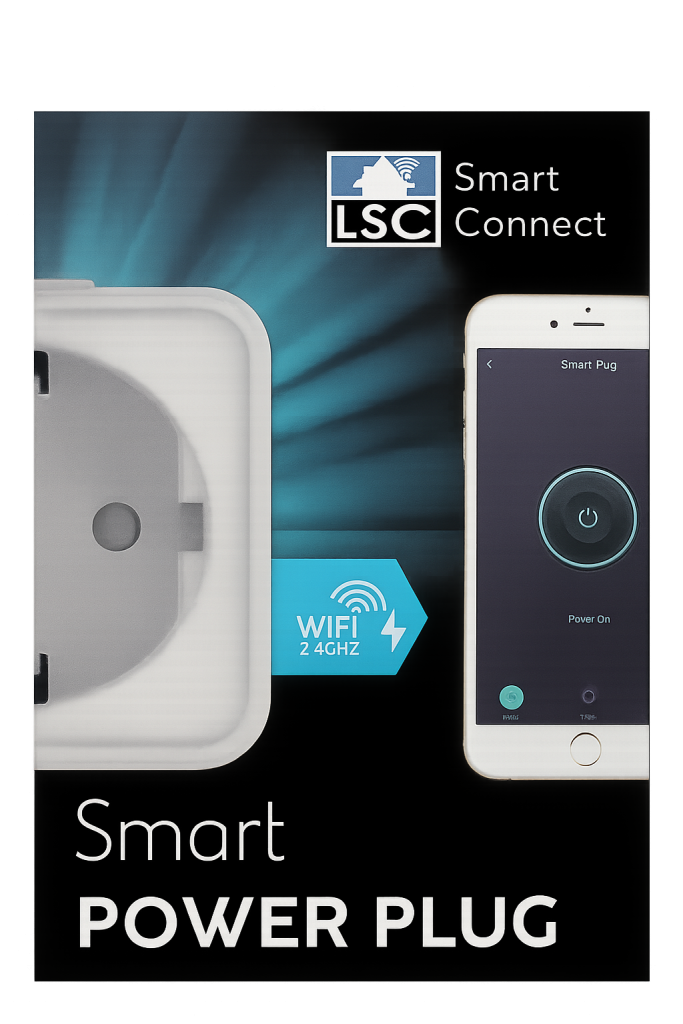
For years, the Dutch retailer Action has offered affordable smart-home devices under the brand LSC Smart Connect .

For years, the Dutch retailer Action has offered affordable smart-home devices under the brand LSC Smart Connect. These products are extremely popular because of their low price, but under the hood, they often use hardware that is surprisingly capable. In earlier generations, many LSC products were based on ESP8266 chips that could easily be reprogrammed. However, newer revisions increasingly use alternative chips with locked firmware or limited documentation, making it harder for enthusiasts to flash custom software.
In this three-part series, we explore three models:
- The classic “old” plug (Previous Blog)
- The newer hardware revision (This blog)
- A model with power monitoring
This article focuses on converting one of these smart plugs into a fully open-source Apple HomeKit-compatible device.
What This Project Covers
In this step-by-step guide, you will learn how to:
- Open the LSC Smart Power Plug safely
- Identify the internal hardware
- Remove the original module
- Flash and prepare an ESP8685-WROOM-03
- Install the ESP32 Life Cycle Manager (LCM)
- Generate a HomeKit QR code
- Flash your own HomeKit firmware
- Pair your device with Apple Home
The end goal? A fully custom, native HomeKit smart plug, without cloud dependency.
Why Modify This Smart Plug?
There are more smart devices than ever, but not all of them truly belong to you. Most budget IoT devices depend on:
- Cloud servers
- Vendor accounts
- Proprietary apps
- Remote infrastructure
- Unknown data collection
This creates the privacy trap: You buy the device, but the manufacturer controls it. If you want to understand the deeper implications of cloud-based IoT products, read this article: Source: Why You (Should or Shouldn't) Buy a Smart Plug from Action
By replacing the firmware, you regain:
- Full privacy
- Local device control
- Firmware ownership
- Offline operation
- No telemetry
- Long-term support independence
Difficulty Level
Rating: 2 / 5 Soldering Irons – Beginner friendly

No advanced electronics background is required, but you should be comfortable with:
- Desoldering and soldering
- Working with small components
- Using a serial flasher
- Command-line tools
⚠️ HIGH VOLTAGE WARNING
⚡ DANGER: MAINS ELECTRICITY CAN KILL
This project involves a device that connects directly to 230V AC power.
Always unplug before opening.
Never work live.
Use insulated tools.
Avoid touching exposed conductors.
Proceed only if you understand electrical risks.
The author accepts no liability for damage, injury, or accidents.
If you are unsure, consult a licensed electrician.
Hardware Used
Product Information
From the box:
- Brand: LSC Smart Connect
- Product: Smart Power Plug
- Article numbers:
- Art. No. 2578685 (on the Box)
- Art. No. 970766 (on the plug it self)
From the device:
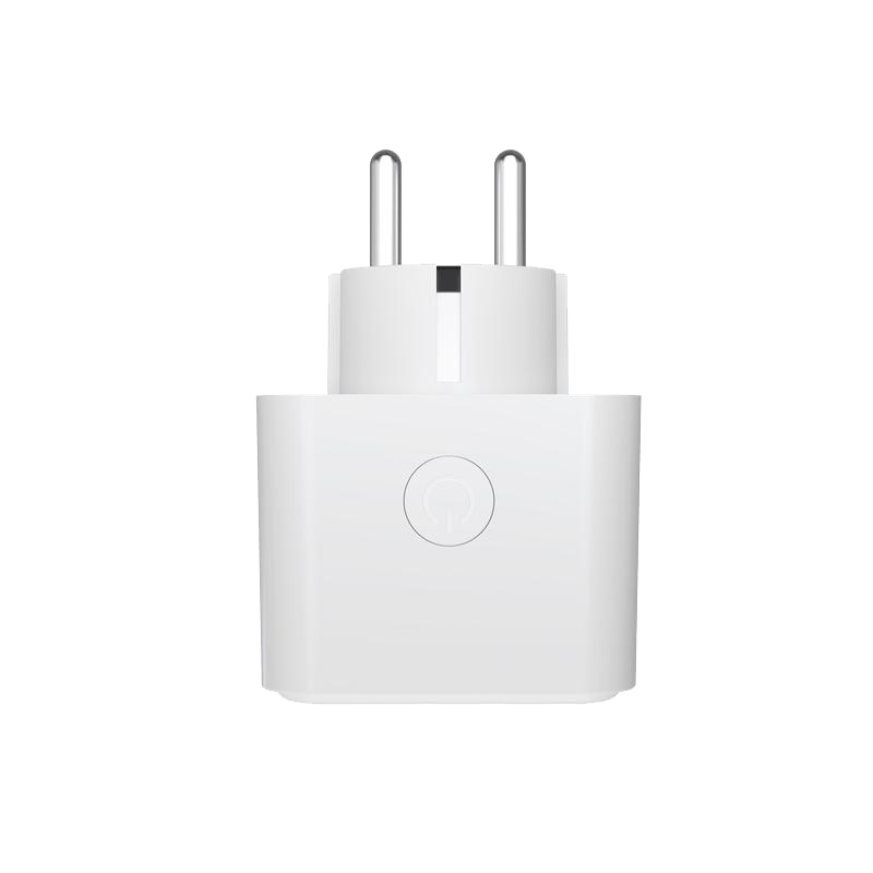
970766 Max 16A 3680W μ T35
220-240V~ 50/60Hz
AL M21167 Made in P.R.C.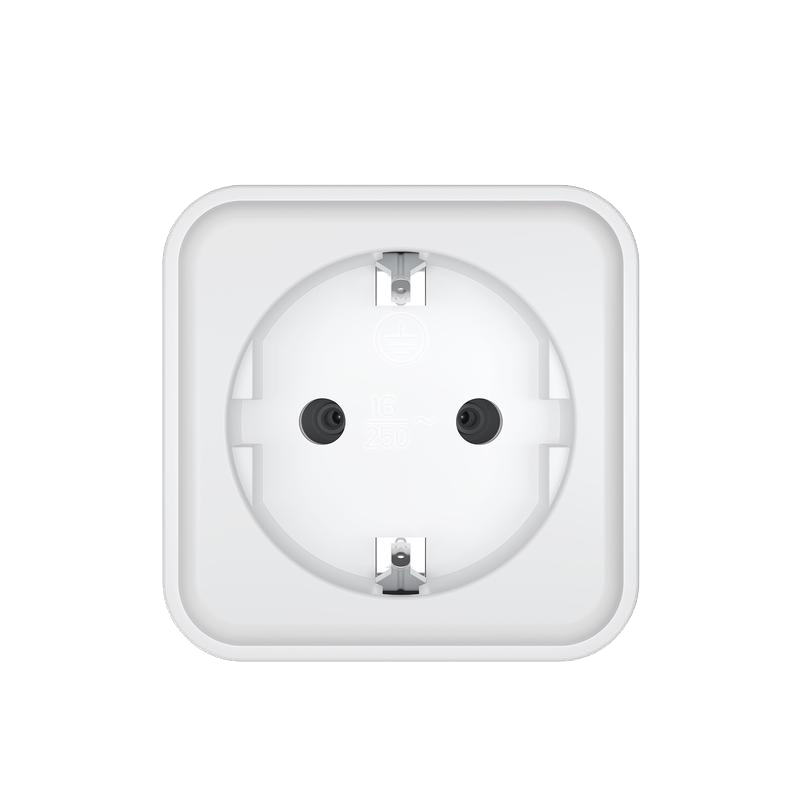
Why We Replace The Chip
The two revisions use different modules:
| Version | Original Chip |
|---|---|
| Art. No. 970766 | CB2S / BK7231N |

The BK7231 is far more difficult to flash and lacks modern ecosystem support. The solution? Replace both with a powerful ESP chip: ESP8685-WROOM-03
This gives you:
- Native HomeKit
- OTA updates
- Full control
- Active community support

Opening the Plug
Tools Required
- Plastic spudgers
- Thin metal pry tool
Steps
- Insert a plastic spudger between the shell halves.
- Create a small gap.
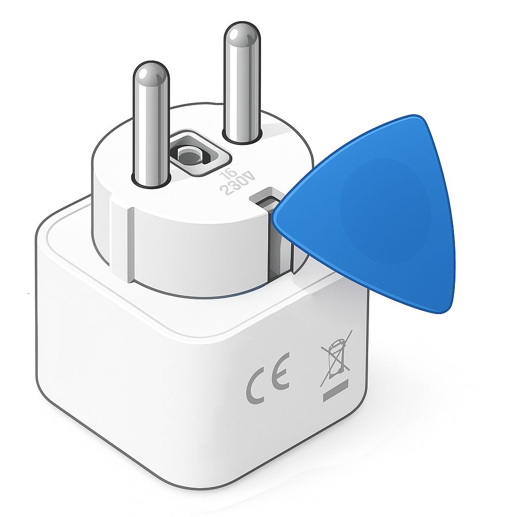
- Slide in a metal spudger.
- Slowly pry toward a corner.
- Release each of the four clips.
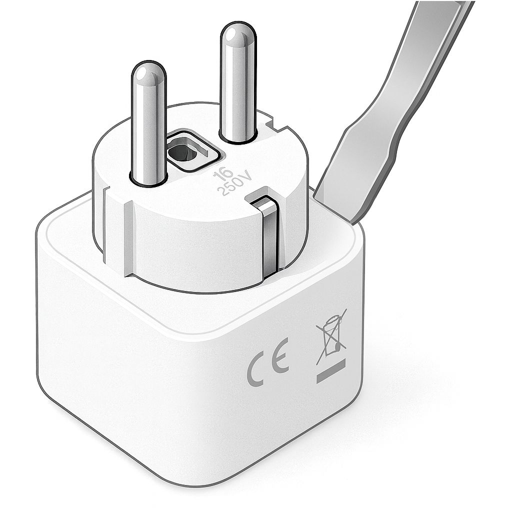
- The shell opens cleanly.
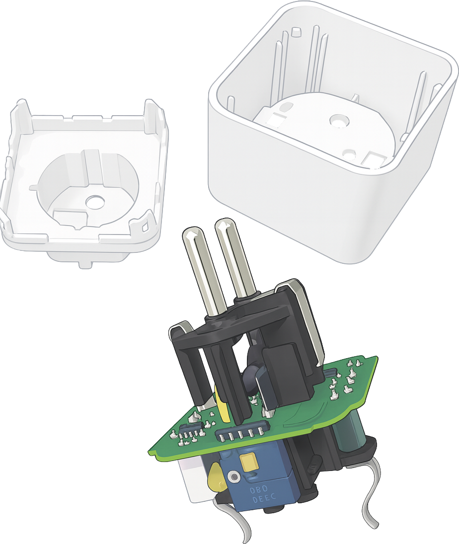
Pin Mapping
After tracing the PCB, this configuration was confirmed:
| Function | WB2S | ESP8685 |
|---|---|---|
| Relay | P6 | GPIO3 |
| Button | P7 | GPIO7 |
| Red LED | P8 | GPIO6 |
| Blue LED | P26 | GPIO4 |
Removing and Decoding the Original Chip
Before installing the new ESP8685-WROOM-03, we first need to safely remove the original module from the PCB. This step is critical: damaging the pads will make the entire project much harder (or impossible). Fortunately, with the right tools, this is a clean and controlled operation.
Tools Required
For this process, I strongly recommend:
- TS100/101 digital soldering iron (or equivalent temperature-controlled iron)
- Desoldering wick / copper braid remover
- Liquid flux (very important!)
- Isopropyl alcohol and cotton swabs
Why the TS100/101? It heats quickly, maintains stable temperature, and is powerful enough for multi-pin modules without overheating the board.

Step 1, Identify the Original Chip
Depending on your plug revision, you will see:
- CB2S / BK7231N
Both are surface-mounted Wi-Fi modules with edge solder pads around the module. Before removal, take high-resolution photos of the PCB from multiple angles. These will be invaluable if anything goes wrong.
Step 2, Add Flux Generously
Apply liquid flux along every solder pad edge of the module.
Flux:
- Lowers melting temperature
- Improves heat transfer
- Prevents pad lifting
- Makes solder flow correctly
Never attempt desoldering without it.
Step 3, Remove the Module
Set the TS100 to 350–380°C.
- Place desoldering braid on one row of pads
- Press with the hot iron
- Let solder absorb into the wick
- Repeat across all sides
- Once all joints are clean, gently lift the module.
Do not pull if resistance remains. Missing even one joint can tear a pad.
Step 4, Clean the Pads
After removal:
- Remove remaining solder with braid
- Clean flux using isopropyl alcohol
- Inspect for lifted pads under magnification
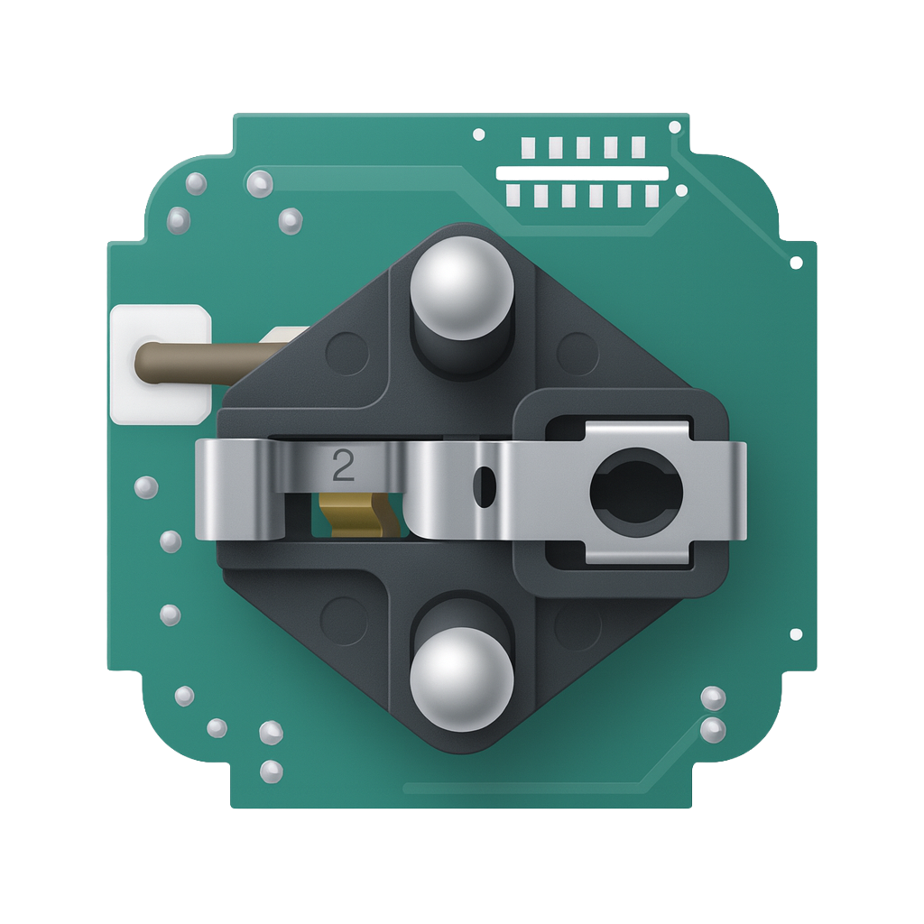
Your board should now show:
- Flat copper pads
- No burned areas
- No solder bridges
- Clean alignment
Preparing the ESP8685
Now that the old module is removed we can prepare the replacement module.
Magnetic Programmer
Instead of soldering headers, I built a magnetic programmer jig, you need a 3D printer. If you do not have a 3D printer you can also solder some wires to the programming pads. source: https://www.studiopieters.nl/esp8685-wroom-03 or 3D printer magnetic programmer jig Source: https://www.studiopieters.nl/esp8685-wroom-03-programmer
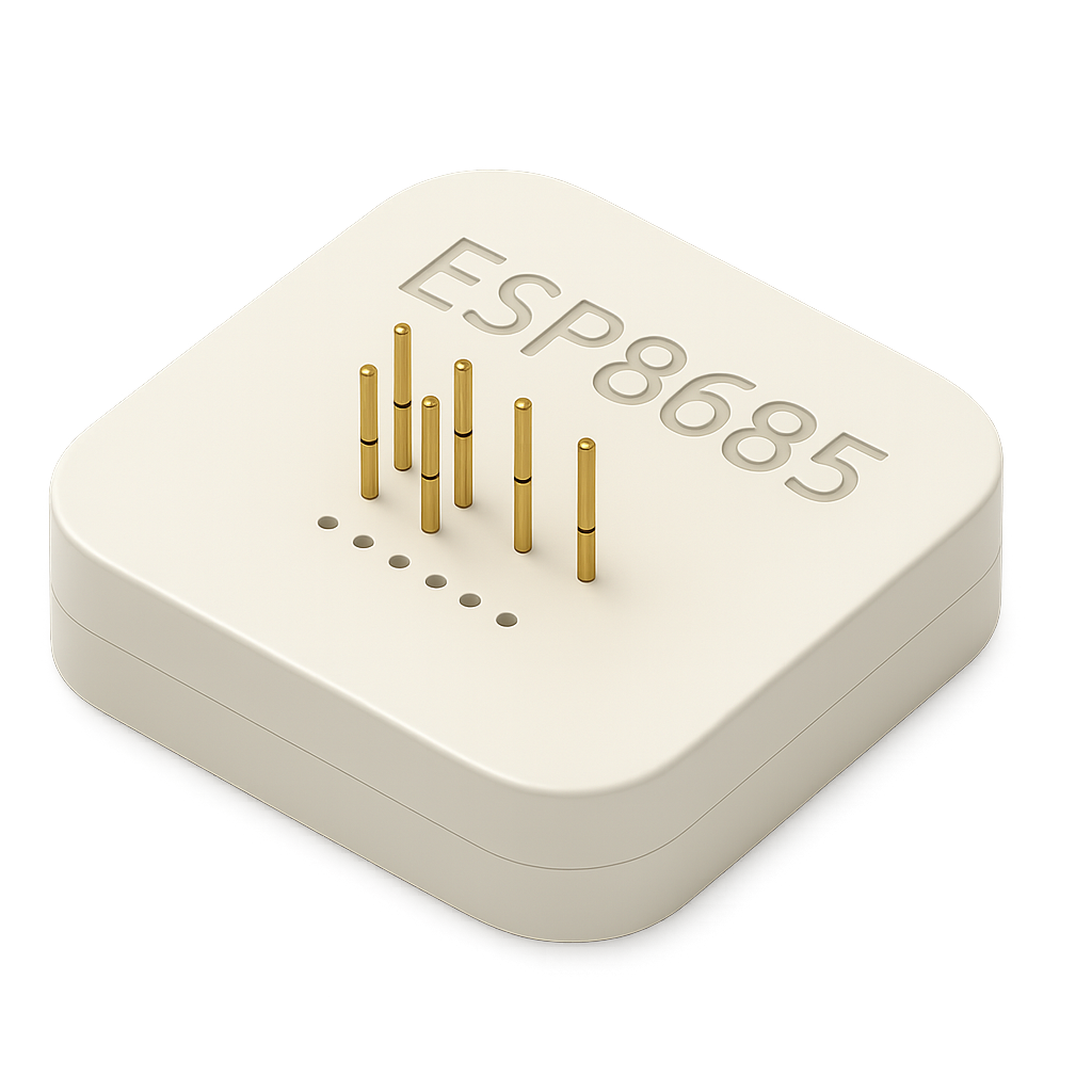

Benefits:
- No soldering
- Stable contact
- Works with esptool
- Fast flashing
- Low risk
Wipe Flash
esptool.py erase_flashExample output:
Chip is ESP32-D0WD-V3
Erasing flash...
Chip erase completed successfully
MAC: 68:25:dd:f0:40:94
⚠️ Save your MAC address , you need it when you generate the QR-Code.
Generate HomeKit QR Code
Do it yourself: Guide to ESP32 HomeKit QR Codes
Do it yourself: https://github.com/AchimPieters/esp32-homekit-qrcode
Example:
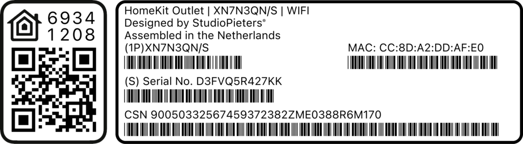
./gen_qrcode 7 693-41-208 M4T8 cc8da2ddafe0 new/qrcode.pngMeanings:
7= Outlet accessory693-41-208= Setup codeM4T8= Setup IDcc8da2ddafe0= MAC (no colons)
This will generate an images like this one. you can use only the QR-code if you want, or the whole image and print it as a sticker, and paste it on your plug.
Or download precompiled qr-code here
Install Life Cycle Manager (LCM)
LCM (Life Cycle Manager) allows OTA (Over The Air) installations and updates without needing to reopening the device ever again!
Do it yourself:https://github.com/AchimPieters/esp32-lifecycle-manager
Or download precompiled files here
Go to the folder where you have placed the files and Flash:
python -m esptool --chip esp32c3 -b 460800 \
--before default_reset --after hard_reset write_flash \
--flash_mode dio --flash_size 4MB --flash_freq 80m \
0x0 build/bootloader/bootloader.bin \
0x8000 build/partition_table/partition-table.bin \
0xe000 build/ota_data_initial.bin \
0x20000 build/esp32-lifecycle-manager.bin
Installing the New Chip and Soldering the ESP8685-WROOM-03
With the old module removed and the pads cleaned, it’s time to install the new brain of your smart plug: the ESP8685-WROOM-03. This is the most delicate part of the entire upgrade, but with patience and the right technique, it’s completely manageable even for beginners.
Step 1, Align and Tack One Corner
- Position the ESP8685 on the footprint (one side 5 and other side 6 pads)
- Align all edges
- Melt one pre-tinned corner pad
- Let it cool

Now check alignment on all sides. If misaligned:
- Reheat the tack joint
- Adjust the module
- Retack once perfect
Step 2, Solder Opposite Corner
Once alignment looks correct:
- Solder the opposite corner
- Check alignment again
Once two corners are fixed, the module will not shift.
Step 3, Drag Soldering the Pads
Apply generous flux along one row of pins.
Now:
- Load a small solder bead on your tip
- Drag slowly across pins
- Let surface tension pull solder into place
- Repeat on the other side
Do not worry if you create bridges, they are easily removed later.
Step 4, Remove Solder Bridges
If pins are shorted together:
- Add flux
- Place desoldering braid
- Lightly press with the iron
- Let solder wick away
- Re-inspect
Your goal:
- Clean joints
- No blobs
- No bridges
- No lifted pads
Step 5, Final Cleaning & Inspection
Clean the board using:
- Isopropyl alcohol
- Cotton swabs
Inspect carefully:
- All pads connected
- No pins floating
- No cold joints
- No heat damage
- No debris
Spend time here. Visual inspection prevents 90{91c9fad616bf0725810074c79079914b0bb05d8bf60d02d56ac06d2922548669} of failures.
Step 6, Continuity Check (Recommended)
Using a multimeter:
- Check no short circuits between neighboring pins
- Confirm ground connections
- Verify relay pin connects to ESP GPIO
- Confirm power rail continuity
This step saves debugging later.
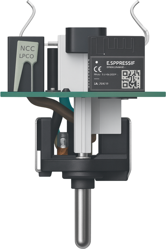
What You’ve Achieved
At this point:
- The old chip is gone
- A modern ESP is installed
- Your firmware control begins
- OTA updates are possible
- Privacy is restored
This is the exact moment your device transitions from: consumer product → personal hardware
Write HomeKit Firmware
This part is somewhat difficult for a beginner, but doable. So if you want to write your own code read the Do it yourself links. If not you can simply use the code I already wrote and compiled, just go to Install via LCM.
Do it yourself: https://github.com/AchimPieters/esp32-homekit
Do it yourself: ESP32 HomeKit Development with ESP-IDF
Config:
homekit_server_config_t config = {
  .accessories = accessories,
  .password = "693-41-208",
.setupId = "M4T8",
};
Build:
docker run -it -v ~/ESP32-Power-Plug:/project -w /project espressif/idf:v5.4idf.py set-target esp32C3idf.py buildProduces: main.bin
View the full source code
/**
   Copyright 2026 Achim Pieters | StudioPieters®

   Permission is hereby granted, free of charge, to any person obtaining a copy
   of this software and associated documentation files (the "Software"), to deal
   in the Software without restriction, including without limitation the rights
   to use, copy, modify, merge, publish, distribute, sublicense, and/or sell
   copies of the Software, and to permit persons to whom the Software is
   furnished to do so, subject to the following conditions:

   The above copyright notice and this permission notice shall be included in all
   copies or substantial portions of the Software.

   THE SOFTWARE IS PROVIDED "AS IS", WITHOUT WARRANTY OF ANY KIND, EXPRESS OR
   IMPLIED, INCLUDING BUT NOT LIMITED TO THE WARRANTIES OF MERCHANTABILITY,
   FITNESS FOR A PARTICULAR PURPOSE AND NON INFRINGEMENT. IN NO EVENT SHALL THE
   AUTHORS OR COPYRIGHT HOLDERS BE LIABLE FOR ANY CLAIM, DAMAGES OR OTHER LIABILITY,
   WHETHER IN AN ACTION OF CONTRACT, TORT OR OTHERWISE, ARISING FROM, OUT OF OR IN
   CONNECTION WITH THE SOFTWARE OR THE USE OR OTHER DEALINGS IN THE SOFTWARE.

   for more information visit https://www.studiopieters.nl
 **/

#include <stdio.h>
#include <esp_log.h>
#include <esp_err.h>
#include <nvs.h>
#include <freertos/FreeRTOS.h>
#include <freertos/task.h>
#include <driver/gpio.h>
#include <homekit/homekit.h>
#include <homekit/characteristics.h>

#include "esp32-lcm.h"
#include <button.h>

// -------- GPIO configuration (set these in sdkconfig) --------
#define BUTTON_GPIO      CONFIG_ESP_BUTTON_GPIO
#define RELAY_GPIO       CONFIG_ESP_RELAY_GPIO
#define BLUE_LED_GPIO    CONFIG_ESP_BLUE_LED_GPIO
#define RED_LED_GPIO     CONFIG_ESP_RED_LED_GPIO   // Rode LED: WiFi/lifecycle-indicator

static const char *RELAY_TAG   = "RELAY";
static const char *BUTTON_TAG  = "BUTTON";
static const char *IDENT_TAG   = "IDENT";

// Relay / plug state (enige bron van waarheid)
static bool relay_on = false;

// ---------- Low-level GPIO helpers ----------

static inline void relay_write(bool on) {
        gpio_set_level(RELAY_GPIO, on ? 1 : 0);
}

static inline void blue_led_write(bool on) {
        // Blauwe LED: uitsluitend als aan/uit-indicator voor de relay (active low/high afhankelijk van hardware)
        gpio_set_level(BLUE_LED_GPIO, on ? 1 : 0);
}

static inline void red_led_write(bool on) {
        // Rode LED is active high: 1 = AAN, 0 = UIT
        gpio_set_level(RED_LED_GPIO, on ? 1 : 0);
}

// Forward declaration van de characteristic zodat we hem in functies kunnen gebruiken
extern homekit_characteristic_t relay_on_characteristic;

// Centrale functie: zet state, stuurt hardware aan en (optioneel) HomeKit-notify
static void relay_set_state(bool on, bool notify_homekit) {
        if (relay_on == on) {
                // Geen verandering, niets te doen
                return;
        }

        relay_on = on;

        // Hardware aansturen
        relay_write(relay_on);
        blue_led_write(relay_on); // Blauwe LED volgt altijd de relay-status

        ESP_LOGI(RELAY_TAG, "Relay state -> %s", relay_on ? "ON" : "OFF");

        // HomeKit characteristic-snapshot updaten
        relay_on_characteristic.value = HOMEKIT_BOOL(relay_on);

        // Eventueel HomeKit-clients informeren
        if (notify_homekit) {
                homekit_characteristic_notify(&relay_on_characteristic,
                                              relay_on_characteristic.value);
        }
}

// All GPIO Settings
void gpio_init(void) {
        // Relay
        gpio_reset_pin(RELAY_GPIO);
        gpio_set_direction(RELAY_GPIO, GPIO_MODE_OUTPUT);

        // Blauwe LED (aan/uit)
        gpio_reset_pin(BLUE_LED_GPIO);
        gpio_set_direction(BLUE_LED_GPIO, GPIO_MODE_OUTPUT);

        // Rode LED: WiFi-status-indicator
        gpio_reset_pin(RED_LED_GPIO);
        gpio_set_direction(RED_LED_GPIO, GPIO_MODE_OUTPUT);

        // Initial state: alles uit, in sync brengen
        relay_on = false;
        relay_on_characteristic.value = HOMEKIT_BOOL(false);
        relay_write(false);
        blue_led_write(false);

        // Bij start is er nog geen WiFi -> rode LED AAN
        red_led_write(true);
}

// ---------- Accessory identification (Blue LED) ----------

void accessory_identify_task(void *args) {
        // Blink BLUE LED to identify, then restore previous state
        bool previous_led_state = relay_on; // LED volgt normaal relay_on

        for (int i = 0; i < 3; i++) {
                for (int j = 0; j < 2; j++) {
                        blue_led_write(true);
                        vTaskDelay(pdMS_TO_TICKS(100));
                        blue_led_write(false);
                        vTaskDelay(pdMS_TO_TICKS(100));
                }
                vTaskDelay(pdMS_TO_TICKS(250));
        }

        // Zet LED terug naar de normale toestand (afhankelijk van relay_on)
        blue_led_write(previous_led_state);

        vTaskDelete(NULL);
}

void accessory_identify(homekit_value_t _value) {
        ESP_LOGI(IDENT_TAG, "Accessory identify");
        xTaskCreate(accessory_identify_task, "Accessory identify", configMINIMAL_STACK_SIZE,
                    NULL, 2, NULL);
}

// ---------- HomeKit characteristics ----------

#define DEVICE_NAME          "HomeKit Plug"
#define DEVICE_MANUFACTURER  "StudioPieters®"
#define DEVICE_SERIAL        "NLCC7DFD193A"
#define DEVICE_MODEL         "LS066NL/A"
#define FW_VERSION           "0.0.1"

homekit_characteristic_t name = HOMEKIT_CHARACTERISTIC_(NAME, DEVICE_NAME);
homekit_characteristic_t manufacturer = HOMEKIT_CHARACTERISTIC_(MANUFACTURER, DEVICE_MANUFACTURER);
homekit_characteristic_t serial = HOMEKIT_CHARACTERISTIC_(SERIAL_NUMBER, DEVICE_SERIAL);
homekit_characteristic_t model = HOMEKIT_CHARACTERISTIC_(MODEL, DEVICE_MODEL);
homekit_characteristic_t revision = HOMEKIT_CHARACTERISTIC_(FIRMWARE_REVISION, LIFECYCLE_DEFAULT_FW_VERSION);
homekit_characteristic_t ota_trigger = API_OTA_TRIGGER;

// Getter: HomeKit vraagt huidige toestand op
homekit_value_t relay_on_get() {
        return HOMEKIT_BOOL(relay_on);
}

// Setter: aangeroepen door HomeKit (Home-app / Siri / automations)
void relay_on_set(homekit_value_t value) {
        if (value.format != homekit_format_bool) {
                ESP_LOGE(RELAY_TAG, "Invalid value format: %d", value.format);
                return;
        }

        bool new_state = value.bool_value;

        // Via centrale functie, maar ZONDER notify (originator is HomeKit zelf)
        relay_set_state(new_state, false);
}

// We keep a handle to ON characteristic so we can notify on button presses
homekit_characteristic_t relay_on_characteristic =
        HOMEKIT_CHARACTERISTIC_(ON, false, .getter = relay_on_get, .setter = relay_on_set);

#pragma GCC diagnostic push
#pragma GCC diagnostic ignored "-Woverride-init"
homekit_accessory_t *accessories[] = {
        HOMEKIT_ACCESSORY(
                .id = 1,
                .category = homekit_accessory_category_outlets, // Smart plug / outlet
                .services = (homekit_service_t *[]) {
                HOMEKIT_SERVICE(ACCESSORY_INFORMATION, .characteristics = (homekit_characteristic_t *[]) {
                        &name,
                        &manufacturer,
                        &serial,
                        &model,
                        &revision,
                        HOMEKIT_CHARACTERISTIC(IDENTIFY, accessory_identify),
                        NULL
                }),
                HOMEKIT_SERVICE(OUTLET, .primary = true, .characteristics = (homekit_characteristic_t *[]) {
                        HOMEKIT_CHARACTERISTIC(NAME, "HomeKit Plug"),
                        &relay_on_characteristic,
                        &ota_trigger,
                        NULL
                }),
                NULL
        }),
        NULL
};
#pragma GCC diagnostic pop

homekit_server_config_t config = {
        .accessories = accessories,
        .password = CONFIG_ESP_SETUP_CODE,
        .setupId = CONFIG_ESP_SETUP_ID,
};

// ---------- Button handling ----------

void button_callback(button_event_t event, void *context) {
        switch (event) {
        case button_event_single_press: {
                ESP_LOGI(BUTTON_TAG, "Single press -> toggle relay");

                bool new_state = !relay_on;

                // 1) Zelfde logica als HomeKit, maar nu MET notify
                relay_set_state(new_state, true);

                break;
        }
        case button_event_double_press:
                // Do nothing, by design
                ESP_LOGI(BUTTON_TAG, "Double press -> no action");
                break;
        case button_event_long_press:
                ESP_LOGI(BUTTON_TAG, "Long press (10s) -> factory reset + reboot");
                lifecycle_factory_reset_and_reboot();
                break;
        default:
                ESP_LOGI(BUTTON_TAG, "Unknown button event: %d", event);
                break;
        }
}

// ---------- Wi-Fi / HomeKit startup ----------

void on_wifi_ready() {
        static bool homekit_started = false;

        // WiFi is nu up -> rode LED uit
        red_led_write(false);

        if (homekit_started) {
                ESP_LOGI("INFORMATION", "HomeKit server already running; skipping re-initialization");
                return;
        }

        ESP_LOGI("INFORMATION", "Starting HomeKit server...");
        homekit_server_init(&config);
        homekit_started = true;
}

// ---------- app_main ----------

void app_main(void) {
        ESP_ERROR_CHECK(lifecycle_nvs_init());
        lifecycle_log_post_reset_state("INFORMATION");
        ESP_ERROR_CHECK(lifecycle_configure_homekit(&revision, &ota_trigger, "INFORMATION"));

        gpio_init();

        button_config_t btn_cfg = button_config_default(button_active_low);
        btn_cfg.max_repeat_presses = 3;
        btn_cfg.long_press_time = 10000; // 10 seconds for lifecycle_factory_reset_and_reboot

        if (button_create(BUTTON_GPIO, btn_cfg, button_callback, NULL)) {
                ESP_LOGE(BUTTON_TAG, "Failed to initialize button");
        }

        esp_err_t wifi_err = wifi_start(on_wifi_ready);
        if (wifi_err == ESP_ERR_NVS_NOT_FOUND) {
                ESP_LOGW("WIFI", "WiFi configuration not found; provisioning required");
                // Geen geldige WiFi-config -> rode LED AAN
                red_led_write(true);
        } else if (wifi_err != ESP_OK) {
                ESP_LOGE("WIFI", "Failed to start WiFi: %s", esp_err_to_name(wifi_err));
                // Fout bij starten WiFi -> rode LED AAN
                red_led_write(true);
        }
}Sign Firmware
Open a new terminal window go to the directory ESP32-Smart_connect_Plug and run:
openssl sha384 -binary -out build/main.bin.sig build/main.bin
printf "{91c9fad616bf0725810074c79079914b0bb05d8bf60d02d56ac06d2922548669}08x" "$(wc -c < build/main.bin)" | xxd -r -p >> build/main.bin.sig
Or just use my repository and read further below.
Install via LCM
- Connect to WiFi:
LCM-XXXXX - Portal opens automatically
- Enter home WiFi credentials
- Firmware source:
AchimPieters/esp32-Power-plug - Enable GPIO6 (Red LED in this case) and Led Level On
- Click Join
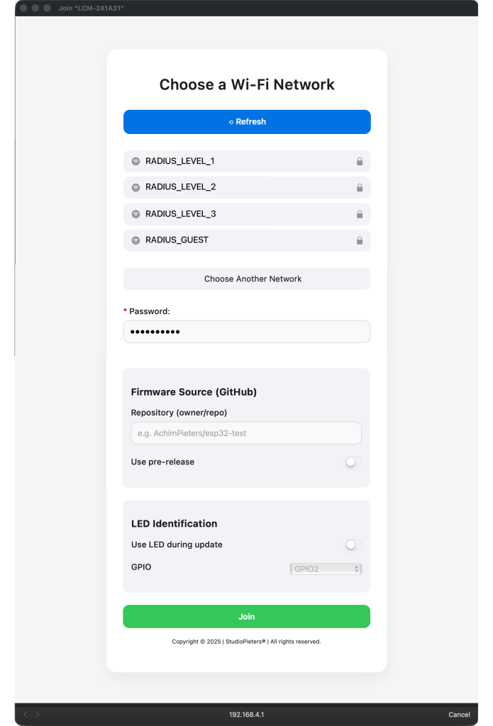
Installation begins, the LED starts blinking. When done the Device reboots.
Pair with Apple Home
Add HomeKit-power plug Devices to HomeKit
- Open the Home app.
- Scan the device's QR-Code.
- Follow the device-specific instructions.
- Name your device and assign it to a room.
Done.
Update Firmware
When You want to update your plug with a new release of the firmware you have to download the EVE App. This because the Home App, doesn't has a building update function. In the Eve App select your device in this case your Power plug and hold it until you see "Turn On" and "Show in (the room you selected)", select the room, here you only see the homkitplu and turn on or off? press between the homekitplug and the on/off option, and a new screen will magically appear here select FirmwareUpdate, this whole takes a few minutes, including the reconnection to HomeKit.
Final Result
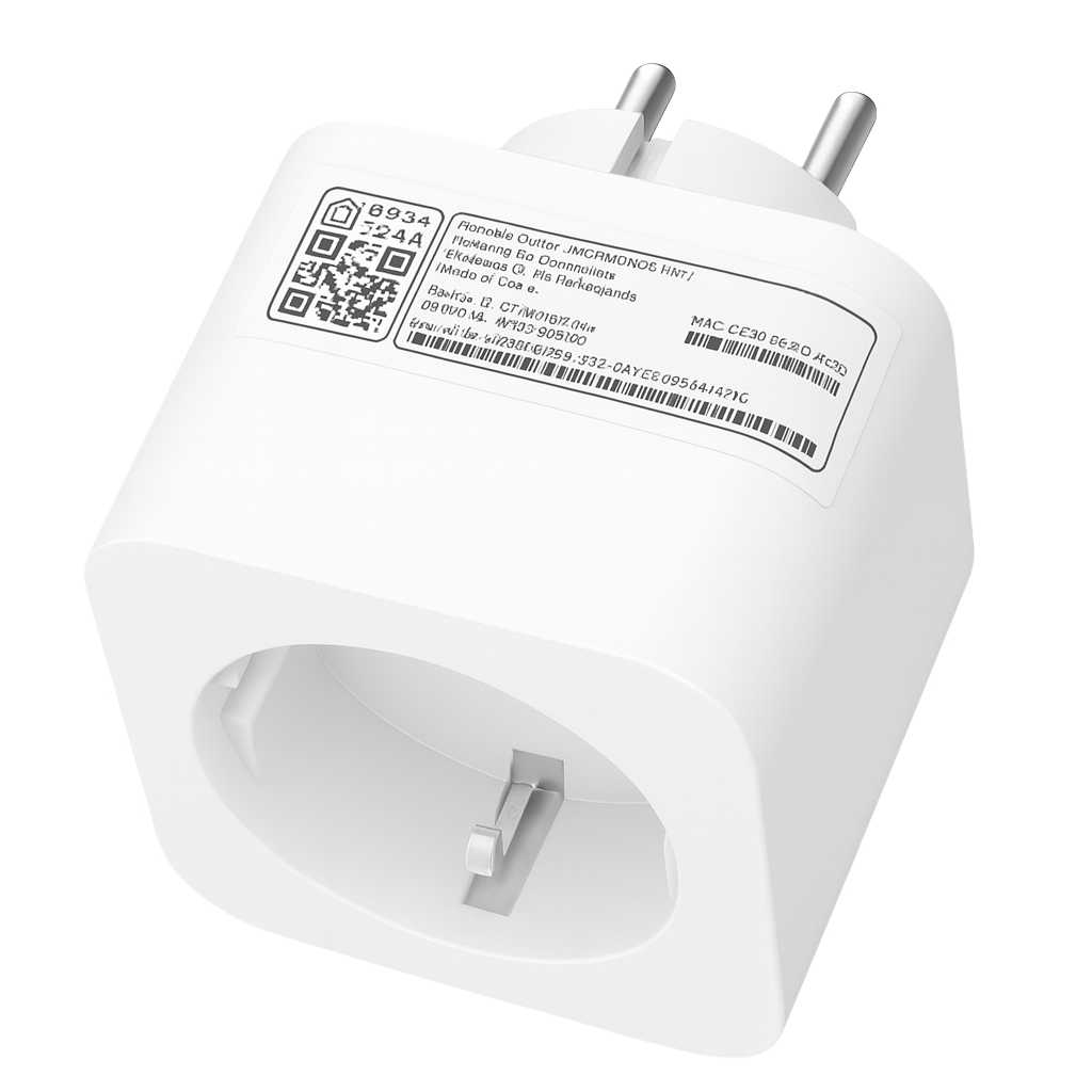
You now have:
- A smart plug you actually own
- OTA upgrades
- No vendor cloud
- Native HomeKit
- Full firmware control
- Open-source system
- No app lock-in
- No spyware
- Lifetime usability
Links & Resources
ESP32 Life Cycle Manager
https://github.com/AchimPieters/esp32-lifecycle-manager
HomeKit QR generator
https://github.com/AchimPieters/esp32-homekit-qrcode
ESP32 HomeKit Framework
https://github.com/AchimPieters/esp32-homekit
More projects:
https://www.studiopieters.nl