The ESP8266-01 is the tiniest, most affordable Wi-Fi microcontroller module in the ESP8266 family. Its minimalist design and ultra-small footprint make it perfect for embedding wireless connectivity into compact devices. Despite having only 8 pins, the ESP-01 can power robust smart home solutions, basic sensors, relays, and automation — all at an unbeatable price. This guide gives you the clearest, most complete reference to the ESP8266-01 pinout, with pro tips for flawless integration.
What is the ESP8266-01?
System-on-Chip (SoC)
Like all ESP8266 modules, the ESP-01 is built around Espressif’s legendary SoC: a single-core Tensilica L106 running at 80 or 160 MHz, integrated Wi-Fi (802.11 b/g/n), and ample flash/RAM for small IoT tasks.
ESP-01 Module
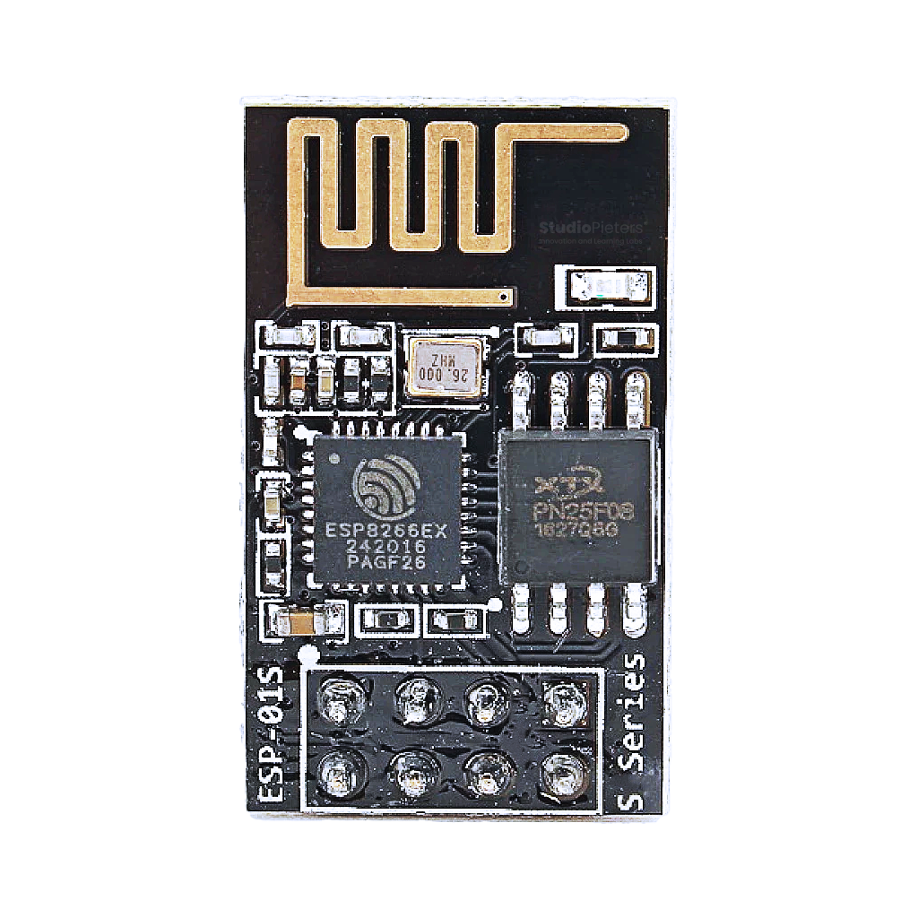
The ESP8266-01 module is famous for its compact, 8-pin DIP form factor. It includes:
- The ESP8266 chip,
- On-board PCB antenna,
- 512 KB or 1 MB flash memory,
- Crystal oscillator,
- Minimal passives.
This is not a development board — just the bare essentials for embedding Wi-Fi in your project.
Why Choose the ESP8266-01?
- Ultra-low cost
- Tiny size — only 24.8 × 14.3 mm!
- Breadboard friendly (with an 8-pin header)
- Wi-Fi ready
- Low-power, perfect for battery IoT
- Ideal for relays, switches, sensors, serial-to-Wi-Fi bridges
Limitations:
Only 2 usable GPIOs, no built-in USB, and limited flash/RAM. It’s minimal — and that’s the point.
ESP8266-01 Pinout Diagram High Resolution

You can download a high-resolution ESP8266-01 pinout at the end of this post — for free!
ESP8266-01 Pinout – GPIO & Function Overview
The ESP8266-01 exposes just 8 pins. Here’s what each does:
| Pin | Label | Function |
|---|---|---|
| 1 | GND | Ground |
| 2 | TX | UART TX (GPIO1) |
| 3 | GPIO2 | Digital I/O, Boot Mode related |
| 4 | CH_PD | Chip Enable (HIGH = On) |
| 5 | RST | Reset (LOW to reset) |
| 6 | GPIO0 | Digital I/O, Boot Mode related |
| 7 | VCC | 3.3V Power Input |
| 8 | RX | UART RX (GPIO3) |
GPIO Details: What You Can and Can’t Do
- GPIO0 (Pin 6): Digital I/O, also used to set boot mode.
- LOW at boot = Programming mode
- HIGH at boot = Run program
- GPIO2 (Pin 3): Digital I/O, must be HIGH at boot.
- LOW at boot = Boot fails!
- CH_PD (EN, Pin 4): Must be tied HIGH (3.3V) for the chip to run.
- TX (GPIO1, Pin 2): UART TX, can be used as output in some firmware.
- RX (GPIO3, Pin 8): UART RX, can be used as input in some firmware.
Note:
- ADC (Analog input) is not available on ESP-01.
- PWM is available on GPIO0 and GPIO2 (firmware dependent).
- I2C (bit-banged) is possible using GPIO0 and GPIO2.
- SPI is not available on ESP-01 (need more pins).
Boot Modes — Critical for ESP-01!
Boot mode is set by the state of GPIO0 and GPIO2 at power-up/reset:
| GPIO0 | GPIO2 | Mode | Use |
|---|---|---|---|
| HIGH | HIGH | Run application | Normal operation |
| LOW | HIGH | Flashing mode | Programming via UART |
| HIGH | LOW | Invalid | Will not boot |
| LOW | LOW | Invalid | Will not boot |
Pro Tip:
- For programming: Hold GPIO0 LOW while resetting or powering on.
- GPIO2 must always be HIGH at boot (pull-up resistor recommended).
ESP8266-01 Power and Programming
Power Requirements
- VCC: 3.0 – 3.6V (3.3V recommended)
- Current: Can draw up to 300 mA during Wi-Fi transmission — use a solid 3.3V regulator!
- DO NOT use 5V directly — it will kill the chip.
Programming
- Serial adapter required! (3.3V logic only, not 5V)
- Connect UART TX/RX from your USB-serial adapter to ESP-01 TX/RX
- Pull CH_PD and GPIO2 HIGH
- Pull GPIO0 LOW to enter programming mode, then pulse RST LOW
ESP8266-01 Quick Reference Table
| Pin | Name | Direction | Default at Boot | Pull-up Needed? | Notes |
|---|---|---|---|---|---|
| 1 | GND | – | – | No | Ground |
| 2 | TX | Output | – | No | UART TX (GPIO1) |
| 3 | GPIO2 | I/O | HIGH | YES | Must be HIGH on boot |
| 4 | CH_PD | Input | HIGH | YES | Tie HIGH to enable chip |
| 5 | RST | Input | HIGH | Pull-up (10kΩ) | LOW to reset |
| 6 | GPIO0 | I/O | HIGH (run) | YES (10kΩ) | LOW to flash, else I/O |
| 7 | VCC | – | 3.3V | – | Power (3.3V) |
| 8 | RX | Input | – | No | UART RX (GPIO3) |
Best Practices and Common Mistakes
- Always use pull-ups (10kΩ) on CH_PD, GPIO0, GPIO2, and RST for stability.
- Don’t use 5V! All signals and power must be 3.3V.
- Never exceed GPIO current limits (~12mA max per pin).
- Program carefully: GPIO0 LOW and GPIO2 HIGH at reset to flash.
- No ADC! — don’t try to connect analog sensors.
- Only 2 usable GPIOs (GPIO0, GPIO2). Plan accordingly!
- Avoid boot pin conflicts: Don’t connect buttons, LEDs, or relays directly to GPIO0/2 without pull-ups and current limiting resistors.
- Stable Power: Provide enough current — brownouts cause random resets.
How to Program the ESP8266-01
Development Environments
- Arduino IDE (using Generic ESP8266 board)
- PlatformIO (with ESP8266 package)
- AT Command firmware (factory default, for Wi-Fi to Serial)
Steps
- Connect ESP-01 to USB-serial adapter (3.3V logic)
- Tie CH_PD, GPIO2 HIGH (3.3V, with 10kΩ pull-up)
- Pull GPIO0 LOW to enter flash mode
- Pulse RST LOW to reset, then upload code via Arduino IDE/PlatformIO
- After flashing, set GPIO0 HIGH and reset to run user code
Conclusion: Tiny, Mighty, Legendary
The ESP8266-01 proves that great things come in small packages. With just 8 pins and 2 usable GPIOs, it’s not a powerhouse — but it’s perfect for compact, Wi-Fi-enabled projects where cost, size, and simplicity are key. Master the ESP-01 pinout, and you’ll have a rock-solid foundation for smart relays, wireless sensors, and low-cost automation.
Download the ESP32 pinout here in high resolution – for free*!
* Free to use under the MIT license — attribution is required.