
Electronics
Arduino Nano HV Rescue Shield
If you’ve ever configured the fuse bits of an ATtiny incorrectly, for example disabling the RESET pin or choosing the wrong clock source, regular ISP programming will fail. Your microcontroller will appear to be bricked .

If you’ve ever configured the fuse bits of an ATtiny incorrectly, for example disabling the RESET pin or choosing the wrong clock source, regular ISP programming will fail. Your microcontroller will appear to be bricked. Luckily, there’s a reliable fix: the Arduino Nano HV Rescue Shield. By applying a 12 V “backdoor” you can reprogram the fuse bits and bring your ATtiny back to life.
What is the HV Rescue Shield?
An HV Rescue Shield is an add-on for (in this case) an Arduino Nano that makes it possible to use High-Voltage Serial Programming (HVSP) to reset the fuse bits of ATtiny microcontrollers. The trick? Supplying 12 V to the RESET pin, which forces the chip into programming mode even if ISP no longer works.
Why do you need this?
- You disabled the RESET pin to use it as a normal I/O.
- Incorrect fuse settings prevent ISP communication.
- HVSP is the only way to restore the factory defaults.
How it works, hardware
Components required:
- Arduino Nano
- 12 V supply (bench supply or DC-DC boost converter)
- P-channel MOSFET (logic-level type, e.g. AO3407A, IRLML6402, IRF9540N)
- Resistors:
- 1 kΩ (series resistor from MOSFET drain to RESET pin)
- 1 kΩ (series resistor from D8 to Gate) - Breadboard or perfboard
- Jumper wires
- (Optional) SOIC test clip for SMD packages

Alternative setup
If you don't have a P-channel MOSFET (logic-level type, e.g. AO3407A, IRLML6402, IRF9540N) you can use a 2N2222 PNP transistor and a Relay, in this case an Omron G5V-1.

Pin Mapping (Arduino Nano → ATtiny85 DIP-8)
| Arduino Nano pin | ATtiny85 pin | Function |
|---|---|---|
| D9 → SDI | Pin 5 | Data In |
| D10 → SII | Pin 6 | Instruction In |
| D11 → SDO | Pin 7 | Data Out |
| D12 → SCI | Pin 2 | Clock |
| D8 → P-MOSFET gate → 12 V → RESET | Pin 1 | 12 V reset pulse (LOW = 12 V ON) |
| +5 V | Pin 8 | VCC |
| GND | Pin 4 | GND (shared with 12 V source ground) |
Important: Use a P-channel MOSFET to connect/disconnect 12 V to the ATtiny RESET pin.
How it works, software (Arduino IDE)
With the hardware ready, we’ll use the HV Rescue sketch to restore safe fuse settings. The Arduino Nano drives the HVSP sequence; you trigger it from the Serial Monitor.
What you need (software)
- Arduino IDE
- This sketch (see code block below), pre-mapped for Nano → ATtiny85
- Serial Monitor set to 9600 baud
View the full source code
/**
   Copyright 2025 Achim Pieters | StudioPieters®

   Permission is hereby granted, free of charge, to any person obtaining a copy
   of this  software and associated documentation files (the "Software"), to deal
   in the Software without restriction, including without limitation the rights
   to use, copy, modify, merge, publish, distribute, sublicense, and/or sell
   copies of the Software, and to permit persons to whom the Software is
   furnished to do so, subject to the following conditions:

   The above copyright notice and this permission notice shall be included in all
   copies or substantial portions of the Software.

   THE SOFTWARE IS PROVIDED "AS IS", WITHOUT WARRANTY OF ANY KIND, EXPRESS OR
   IMPLIED, INCLUDING BUT NOT LIMITED TO THE WARRANTIES OF MERCHANTABILITY,
   FITNESS FOR A PARTICULAR PURPOSE AND NON INFRINGEMENT. IN NO EVENT SHALL THE
   AUTHORS OR COPYRIGHT HOLDERS BE LIABLE FOR ANY CLAIM, DAMAGES OR OTHER LIABILITY,
   WHETHER IN AN ACTION OF CONTRACT, TORT OR OTHERWISE, ARISING FROM, OUT OF OR IN
   CONNECTION WITH THE SOFTWARE OR THE USE OR OTHER DEALINGS IN THE SOFTWARE.

   for more information visit https://www.studiopieters.nl
 **/

// AVR High-voltage Serial Programmer trough Nano→ATtiny85
// Writes LFUSE=0x62 and HFUSE=0xDF. EFUSE is read only. Baud: 9600.
//
// Nano → ATtiny85 DIP-8:
// D9  → SDI  (pin 5)
// D10 → SII  (pin 6)
// D11 → SDO  (pin 7)
// D12 → SCI  (pin 2)
// D13 → 12V switch → RESET (pin 1)
// 5V → VCC (pin 8), GND → GND (pin 4)

#define HFUSE 0xDF
#define LFUSE 0x62

#define HV_RESET_CTRL 8
#define PIN_SCI       12
#define PIN_SDO       11
#define PIN_SII       10
#define PIN_SDI        9

#define HV_ACTIVE_LOW 1 // HIGH = 12V off, LOW = 12V on (typical NPN transistor setup)

int inByte = 0;
int inData = 0;

void setup() {
  pinMode(HV_RESET_CTRL, OUTPUT);
  pinMode(PIN_SDI, OUTPUT);
  pinMode(PIN_SII, OUTPUT);
  pinMode(PIN_SCI, OUTPUT);
  pinMode(PIN_SDO, OUTPUT);

#if HV_ACTIVE_LOW
  digitalWrite(HV_RESET_CTRL, HIGH); // 12V off
#else
  digitalWrite(HV_RESET_CTRL, LOW);
#endif

  Serial.begin(9600);
  establishContact();
}

void loop() {
  if (Serial.available() > 0) {
    inByte = Serial.read();
    Serial.println();
    Serial.println(F("Entering programming Mode"));

    pinMode(PIN_SDO, OUTPUT);
    digitalWrite(PIN_SDI, LOW);
    digitalWrite(PIN_SII, LOW);

#if HV_ACTIVE_LOW
    digitalWrite(HV_RESET_CTRL, HIGH);
#else
    digitalWrite(HV_RESET_CTRL, LOW);
#endif

    delayMicroseconds(20);

#if HV_ACTIVE_LOW
    digitalWrite(HV_RESET_CTRL, LOW);  // 12V on
#else
    digitalWrite(HV_RESET_CTRL, HIGH); // 12V on
#endif
    delayMicroseconds(10);

    pinMode(PIN_SDO, INPUT);
    delayMicroseconds(300);

    readFuses();

    Serial.println(F("Writing hfuse"));
    shiftOut2(PIN_SDI, PIN_SII, PIN_SCI, MSBFIRST, 0x40, 0x4C);
    shiftOut2(PIN_SDI, PIN_SII, PIN_SCI, MSBFIRST, HFUSE, 0x2C);
    shiftOut2(PIN_SDI, PIN_SII, PIN_SCI, MSBFIRST, 0x00, 0x74);
    shiftOut2(PIN_SDI, PIN_SII, PIN_SCI, MSBFIRST, 0x00, 0x7C);

    Serial.println(F("Writing lfuse"));
    shiftOut2(PIN_SDI, PIN_SII, PIN_SCI, MSBFIRST, 0x40, 0x4C);
    shiftOut2(PIN_SDI, PIN_SII, PIN_SCI, MSBFIRST, LFUSE, 0x2C);
    shiftOut2(PIN_SDI, PIN_SII, PIN_SCI, MSBFIRST, 0x00, 0x64);
    shiftOut2(PIN_SDI, PIN_SII, PIN_SCI, MSBFIRST, 0x00, 0x6C);

    readFuses();

    Serial.println(F("Exiting programming Mode"));
    Serial.println();

#if HV_ACTIVE_LOW
    digitalWrite(HV_RESET_CTRL, HIGH); // 12V off
#else
    digitalWrite(HV_RESET_CTRL, LOW);
#endif
  }
}

void establishContact() {
  while (Serial.available() <= 0) {
    Serial.println(F("Enter a character to continue"));
    delay(800);
  }
}

int shiftOut2(uint8_t dataPin, uint8_t instPin, uint8_t clockPin,
              uint8_t bitOrder, byte valData, byte valInst) {
  int inBits = 0;

  while (!digitalRead(PIN_SDO));

  digitalWrite(PIN_SDI, LOW);
  digitalWrite(PIN_SII, LOW);
  digitalWrite(clockPin, HIGH);
  digitalWrite(clockPin, LOW);

  for (int i = 0; i < 8; i++) {
    if (bitOrder == LSBFIRST) {
      digitalWrite(dataPin,  !!(valData & (1 << i)));
      digitalWrite(instPin,  !!(valInst & (1 << i)));
    } else {
      digitalWrite(dataPin,  !!(valData & (1 << (7 - i))));
      digitalWrite(instPin,  !!(valInst & (1 << (7 - i))));
    }
    inBits <<= 1;
    inBits |= digitalRead(PIN_SDO);
    digitalWrite(clockPin, HIGH);
    digitalWrite(clockPin, LOW);
  }

  digitalWrite(PIN_SDI, LOW);
  digitalWrite(PIN_SII, LOW);
  digitalWrite(clockPin, HIGH);
  digitalWrite(clockPin, LOW);
  digitalWrite(clockPin, HIGH);
  digitalWrite(clockPin, LOW);

  return inBits;
}

void readFuses() {
  shiftOut2(PIN_SDI, PIN_SII, PIN_SCI, MSBFIRST, 0x04, 0x4C);
  shiftOut2(PIN_SDI, PIN_SII, PIN_SCI, MSBFIRST, 0x00, 0x68);
  inData = shiftOut2(PIN_SDI, PIN_SII, PIN_SCI, MSBFIRST, 0x00, 0x6C);
  Serial.print(F("lfuse reads as "));
  Serial.println(inData, HEX);

  shiftOut2(PIN_SDI, PIN_SII, PIN_SCI, MSBFIRST, 0x04, 0x4C);
  shiftOut2(PIN_SDI, PIN_SII, PIN_SCI, MSBFIRST, 0x00, 0x7A);
  inData = shiftOut2(PIN_SDI, PIN_SII, PIN_SCI, MSBFIRST, 0x00, 0x7E);
  Serial.print(F("hfuse reads as "));
  Serial.println(inData, HEX);

  shiftOut2(PIN_SDI, PIN_SII, PIN_SCI, MSBFIRST, 0x04, 0x4C);
  shiftOut2(PIN_SDI, PIN_SII, PIN_SCI, MSBFIRST, 0x00, 0x6A);
  inData = shiftOut2(PIN_SDI, PIN_SII, PIN_SCI, MSBFIRST, 0x00, 0x6E);
  Serial.print(F("efuse reads as "));
  Serial.println(inData, HEX);
  Serial.println();
}Step 1, Set up Arduino IDE
- Go to Tools → Board → select Arduino Nano.
- Tools → Processor → ATmega328P (Old Bootloader) (for most Nano clones).
- Tools → Port → select your Nano’s COM port.
- Later, set Serial Monitor baud rate to 9600.
Step 2, Create a new sketch
- In Arduino IDE: File → New.
- Copy the full sketch below and paste it into the blank file.
- Save As…
HV_Rescue_AttinyXX.
The sketch writes LFUSE = 0x62 and HFUSE = 0xDF (enough to unbrick). EFUSE is read only (usually already 0xFF).
Step 3, Upload
Click Upload and wait until “Done uploading”.
Step 4, Run the rescue
- Double-check wiring, especially D8 → 12 V → RESET.
- Open Serial Monitor (9600 baud).
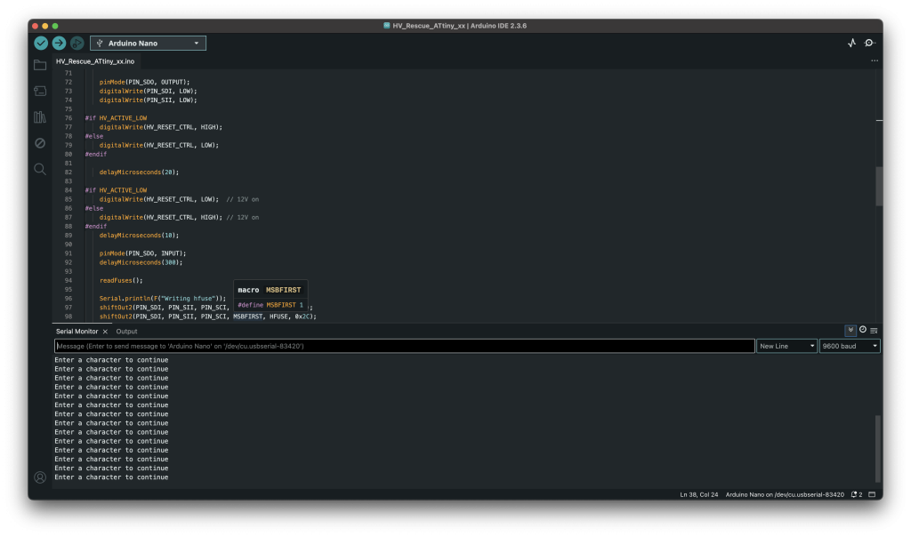
- You’ll see:
Enter a character to continue→ press any key.
- The Nano will:
- briefly apply 12 V to RESET (via D8),
- read the ATtiny signature and current fuses,
- write LFUSE 0x62 and HFUSE 0xDF,
- read them back for verification.
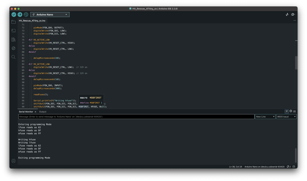
Signs of success in Serial Monitor:
- Signature like
1E 93 0B/0C/0D(ATtiny25/45/85) - Messages: “Writing hfuse/lfuse”
- Fuse reads like:
lfuse reads as 62,hfuse reads as DF - “Exiting programming Mode”
Step 5, Back to ISP
- Remove the chip from the rescue setup.
- Connect your usual ISP programmer.
- Read the fuses again (just to confirm).
- Flash your project as normal.
- (Optional) Set EFUSE to
0xFFvia ISP, usually already correct, not required for unbricking.
Troubleshooting
- No text / gibberish? Serial Monitor not at 9600 baud or wrong COM port.
- Signature 0xFF / 0x00? Check SDI/SII/SDO/SCI wiring, chip orientation, and GND.
- Fuse verify fails? Ensure D8 really switches ~12 V to RESET during rescue.
- 12 V logic inverted? Swap HIGH/LOW logic for D8 in the sketch.
Why this shield is essential
- Unbricks ATtiny chips: Restore ISP access by resetting the RESET pin and fuse bits.
- Low-cost solution: Arduino Nano + a handful of components.
- Safe and repeatable: 12 V is only applied during the fuse programming sequence.
- Future-proof: Perfect tool for experimenting with fuse settings without fear of bricking chips permanently.
Conclusion
With an Arduino Nano HV Rescue Shield, you can easily revive “bricked” ATtiny microcontrollers. The combination of a 12 V reset pulse, serial communication, and a simple Arduino sketch makes this a powerful yet accessible solution.