The DRV8825 is one of the most popular stepper motor drivers in the world of embedded systems. Engineered for precision and control, it’s widely used in 3D printers, CNC machines, robotics, and countless other applications where accurate motion is essential. Whether you’re a beginner or an experienced maker, the DRV8825 provides everything you need to drive motors reliably — smoothly and efficiently. In this guide, you’ll learn everything about the DRV8825 pinout.
What is the DRV8825?
Stepper Motor Driver IC
The DRV8825 is an integrated driver developed by Texas Instruments, designed specifically for controlling bipolar stepper motors. It offers up to 1/32 microstepping, automatic current decay modes, thermal protection, and a maximum current output of 2.5A (with sufficient cooling).
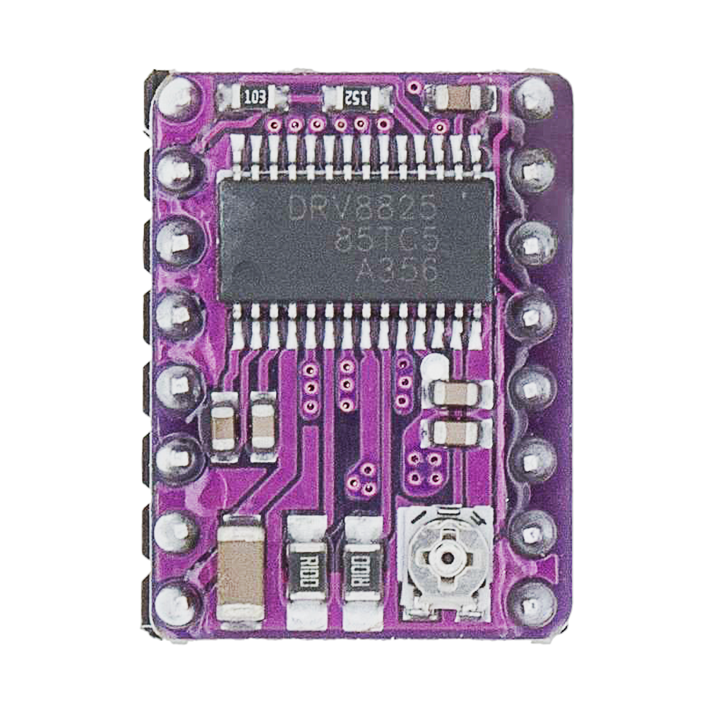
Breakout Module
The most commonly used version of the DRV8825 is the breakout module, such as the one manufactured by Pololu. This breakout exposes the DRV8825’s pins, adds onboard regulation, and integrates components for easy connection to microcontrollers like the Arduino or controller boards like RAMPS.
Built for Precision Control
The DRV8825 provides a powerful combination of flexibility and control:
- Up to 2.5A per coil with heatsinking
- Up to 1/32 microstepping resolution
- Input voltage range: 8.2V to 45V
- Adjustable current limiting
- Sleep and reset control pins
- Over-temperature and over-current protection
- Compatible with both 3.3V and 5V logic
With these features, the DRV8825 is ideal for any application where precise movement is required.

** The DVR8825 pinout is available for download at the end of this post in high resolution – for free!
DRV8825 Pinout – Overview and Functions
The DRV8825 module has 16 pins, split across both sides. Each pin serves a specific purpose crucial for proper operation and optimal performance.
| Pin | Name | Function |
|---|---|---|
| 1 | GND | Logic ground |
| 2 | VMA | Motor power supply A (8.2 V to 45 V) |
| 3 | 2B | Motor coil B (output 2B) |
| 4 | 2A | Motor coil B (output 2A) |
| 5 | 1A | Motor coil A (output 1A) |
| 6 | 1B | Motor coil A (output 1B) |
| 7 | GND | Motor ground |
| 8 | VMOT | Motor power supply (same as VMA) |
| 9 | DIR | Direction input — sets motor rotation direction |
| 10 | STEP | Step input — advances the motor by one step |
| 11 | SLEEP | Sleep mode (active high — LOW disables the driver) |
| 12 | RESET | Reset input (active low — resets internal logic) |
| 13 | MS1 | Microstepping selection bit 1 |
| 14 | MS2 | Microstepping selection bit 2 |
| 15 | MS3 | Microstepping selection bit 3 |
| 16 | EN | Enable input (active low — enables motor outputs) |
Note: In some DRV8825 pinout diagrams, the left and right pin rows are shown mirrored. Always identify pin 1 by locating the notch or printed marking on the board before making connections.
Pin Function Details
Motor Outputs
- 1A / 1B and 2A / 2B are the two coil pairs of your bipolar stepper motor.
- Always ensure correct coil pairing to avoid jittery or stalled movement.
Power Inputs
- VMOT supplies motor voltage — 8.2V to 45V recommended.
- VMA often connected to VMOT on breakout boards.
- Use a 100μF or larger capacitor across VMOT and GND to absorb voltage spikes.
Control Pins
- STEP: Each rising edge triggers one motor step.
- DIR: Sets the direction of rotation.
- EN: Active LOW — enables outputs.
- RESET: Often tied to SLEEP to simplify control.
- SLEEP: LOW disables driver — use a pull-up if not actively controlled.
Microstepping Configuration
The DRV8825 supports up to 1/32 microstepping resolution using three selector pins:
| MS1 | MS2 | MS3 | Microstepping Mode |
|---|---|---|---|
| Low | Low | Low | Full step |
| High | Low | Low | Half step |
| Low | High | Low | 1/4 step |
| High | High | Low | 1/8 step |
| Low | Low | High | 1/16 step |
| High | Low | High | 1/32 step |
Set these pins HIGH or LOW using microcontroller outputs or with pull-up/down resistors.
Current Limiting
The DRV8825 allows current limiting via an onboard potentiometer connected to an internal sense resistor (typically 0.1Ω). This protects both the driver and your stepper motor.
Current calculation:
Imax = Vref × 2Where:
- Imax = Maximum current per coil
- Vref = Voltage between potentiometer and GND
Example: Vref = 0.75V → Imax = 1.5A
Use a multimeter and insulated screwdriver to adjust.

Best Practices and Common Mistakes
✔ Use heatsinks and active cooling when exceeding 1A per coil
✔ Fuse your power input for protection
✔ Tie RESET and SLEEP together if not using separately
✔ Always add a decoupling capacitor across VMOT and GND
✔ Calibrate the current limit for your specific motor specs
✘ Never connect/disconnect motors while powered
✘ Don’t mix motor coil pairs
✘ Don’t forget to pull SLEEP HIGH if used
How to Control the DRV8825
Microcontroller Integration
The DRV8825 works seamlessly with:
- Arduino IDE (using
AccelStepperorStepper.h) - ESP32 / ESP8266 (3.3V logic compatible)
- Raspberry Pi (via GPIO with pull-ups)
- GRBL CNC boards (drop-in compatible with A4988)
Example Code (Arduino):
cppCopyEdit#define STEP_PIN 3
#define DIR_PIN 4

void setup() {
  pinMode(STEP_PIN, OUTPUT);
  pinMode(DIR_PIN, OUTPUT);
  digitalWrite(DIR_PIN, HIGH);
}

void loop() {
  digitalWrite(STEP_PIN, HIGH);
  delayMicroseconds(500);
  digitalWrite(STEP_PIN, LOW);
  delayMicroseconds(500);
}
Conclusion: Precision in Motion
The DRV8825 is a masterclass in modern motion control. Its precision, durability, and versatility make it the go-to driver for countless motor-based projects. Understanding the DRV8825 pinout unlocks smooth, accurate movement — from desktop CNCs to robotic arms and beyond.
Happy Building!
Download the DVR8825 pinout here in high resolution – for free*!
* Free to use under the MIT license — attribution is required.