The ESP32-C6 DevKitC-1 V1.0 is a powerful new development board based on Espressif’s groundbreaking ESP32-C6-WROOM-1 module. This chip is the first in Espressif’s lineup to feature Wi-Fi 6, Bluetooth 5, and IEEE 802.15.4 (for Zigbee & Thread) all in one SoC. With native USB, RISC-V architecture, and secure IoT features, the ESP32-C6 is designed for tomorrow’s wireless world. It is also suitable for ESP32 HomeKit Development. In this guide, you’ll learn everything about the ESP32-C6 pinout and onboard features to help you build smarter — faster.
What is the ESP32-C6?
System-on-Chip (SoC):
The ESP32-C6 features a 32-bit RISC-V single-core processor running at 160 MHz. Unlike earlier Xtensa-based ESP32s, the C6 brings support for:
- Wi-Fi 6 (802.11ax)
- Bluetooth 5 (LE)
- IEEE 802.15.4 (Zigbee / Thread)
- USB 1.1 full-speed device
- Secure boot + flash encryption
This makes it ideal for low-power, highly connected IoT devices.
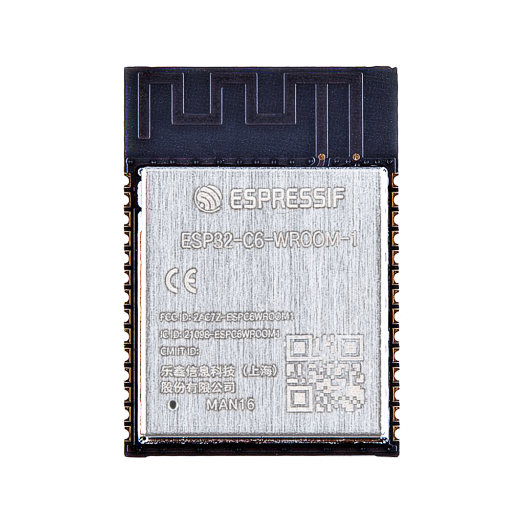
Module:
The board uses the ESP32-C6-WROOM-1 module, combining the C6 chip, 4–8MB flash, crystal, PCB antenna, and passives — pre-certified for FCC/CE and ready for production designs.
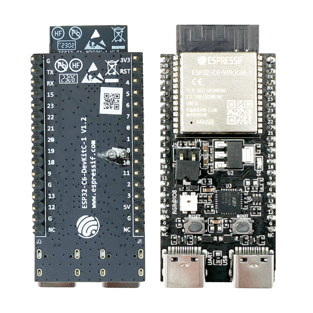
Development Board (DevKit):
The DevKitC-1 V1.0 offers:
- Dual USB-C ports (UART + USB)
- Onboard WS2812 RGB LED on GPIO8
- BOOT and RESET buttons
- Full GPIO breakout with clearly labeled headers
- CH343 USB-to-serial chip
Designed for the Future of IoT
The ESP32-C6 supports:
- RISC-V CPU at 160 MHz
- Wi-Fi 6 (2.4GHz)
- BLE 5 and Mesh
- Zigbee / Thread (802.15.4)
- 24 GPIOs
- USB 1.1 device support
- UART, I2C, SPI, PWM, ADC
- Secure boot / encryption
- Native RGB LED support
- Low-power modes for deep sleep

** The ESP32 pinout is available for download at the end of this post in high resolution – for free!
ESP32-C6 Pinout – GPIO Fundamentals
This dev board exposes 24 GPIO’s, many of which are fully multifunctional. You’ll find support for everything from analog inputs and PWM to UART, SPI, and I2C.
Onboard WS2812 RGB LED
The addressable RGB LED is connected to GPIO8.
Applications:
Use it to indicate Wi-Fi connection status, show HomeKit pairing state, or create colorful animations.
Control it using FastLED or Adafruit_NeoPixel.
ADC – Analog to Digital Converter
The ESP32-C6 includes a 12-bit ADC with 8 channels:
ADC Channels:
- ADC1: GPIO0, GPIO1, GPIO2, GPIO3, GPIO4, GPIO5, GPIO6
- ADC2: GPIO9
Perfect for reading sensors, sliders, or analog voltage levels.
PWM (Pulse Width Modulation)
PWM is available on almost all GPIO’s.
Use cases: dimming LED’s, controlling motors, tone generation, etc.
I2C & SPI Communication
I2C
I2C is software-configurable. Typical setup:
- SDA – GPIO8
- SCL – GPIO9
Use Wire.begin(SDA, SCL); to reconfigure.

SPI
Also fully software-assignable. Example config:
- MOSI – GPIO5
- MISO – GPIO4
- SCLK – GPIO6
- CS – GPIO7

UART and USB Communication
UART
The USB-to-serial interface (CH343) connects to:
- TXD – GPIO17
- RXD – GPIO18
Used for programming and debugging via the UART USB-C port.
USB (Native)
The second USB-C port uses native USB support via:
- USB D+ – GPIO19
- USB D− – GPIO20
Ideal for HID devices, USB CDC, or firmware updates.
ESP32-C6 GPIO Quick Reference Table
| GPIO | Function | ADC | PWM | Notes |
|---|---|---|---|---|
| 0 | ADC1_CH0 | Yes | Yes | Boot strapping pin |
| 1 | ADC1_CH1 | Yes | Yes | |
| 2 | ADC1_CH2 | Yes | Yes | |
| 3 | ADC1_CH3 | Yes | Yes | |
| 4 | SPI MISO | ADC1_CH4 | Yes | Can be used as SDA (I2C) |
| 5 | SPI MOSI | ADC1_CH5 | Yes | Can be used as SCL (I2C) |
| 6 | SPI CLK | ADC1_CH6 | Yes | |
| 7 | SPI CS | No | Yes | |
| 8 | RGB LED / SDA | No | Yes | Onboard NeoPixel |
| 9 | SCL | ADC2_CH1 | Yes | I2C SCL, second ADC |
| 12 | GPIO | No | Yes | |
| 13 | GPIO | No | Yes | |
| 15 | GPIO | No | Yes | |
| 16 | GPIO | No | Yes | |
| 17 | UART TXD | No | Yes | UART via CH343 |
| 18 | UART RXD | No | Yes | UART via CH343 |
| 19 | USB D+ | No | Yes | Native USB |
| 20 | USB D− | No | Yes | Native USB |
| 21 | GPIO | No | Yes | |
| 22 | GPIO | No | Yes | |
| 23 | GPIO | No | Yes | May not be available on all boards |
Best Practices and Common Mistakes
- Avoid using GPIO0 for output during boot — it’s a strapping pin.
- GPIO8 is tied to the onboard NeoPixel — don’t repurpose unless disabled.
- Always debounce buttons in software.
- Pull-up or pull-down resistors may be needed for floating inputs.
- Don’t overload GPIOs: max ~12mA sink/source.
- Use the UART USB-C for flashing; USB USB-C for native device communication.
How to Program the ESP32-C6
Development Environments
- Arduino IDE – (ESP32-C6 support via board manager)
- PlatformIO – Best for multi-project workspaces
- ESP-IDF – Espressif’s official low-level SDK
Programming Pins
| Function | Pin | Description |
|---|---|---|
| TXD0 | GPIO17 | Serial output to PC |
| RXD0 | GPIO18 | Serial input from PC |
| IO0 | GPIO0 | BOOT mode when pulled LOW |
| EN | EN pin | Reset the ESP32-C6 |
Steps:
- Connect the UART USB-C port.
- Select ESP32C6 Dev Module in Arduino/PlatformIO.
- Press “Upload.” Hold BOOT if flashing fails.
Conclusion: Built for the Next Generation
With Wi-Fi 6, BLE 5, and Thread/Zigbee in one chip, the ESP32-C6 is the ultimate low-power wireless SoC. The DevKitC-1 V1.0 board makes development effortless with full pinout access, dual USB, and onboard RGB feedback. If you’re building for the connected future — this board is your launchpad.
Happy Building!
Download the ESP32- C6 pinout here in high resolution – for free*!
* Free to use under the MIT license — attribution is required.