The AI-C3 is a compact and powerful ESP32-C3 development board, designed for modern wireless applications. With its eye-catching purple PCB, onboard USB-C port, addressable RGB LED, and clean pin labeling, the AI-C3 is perfect for getting started with the ESP32-C3 or building embedded projects that require Wi-Fi and BLE. In this guide, you’ll learn everything about the AI-C3 pinout.
What is the AI-C3?
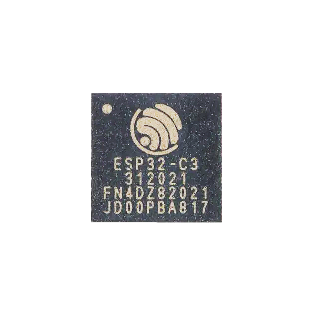
System-on-Chip (SoC)
At its core, the AI-C3 features the ESP32-C3, a RISC-V-based chip from Espressif Systems. It combines 2.4GHz Wi-Fi, Bluetooth 5.0 LE, secure boot, flash encryption, and ultra-low power consumption for IoT and smart devices.
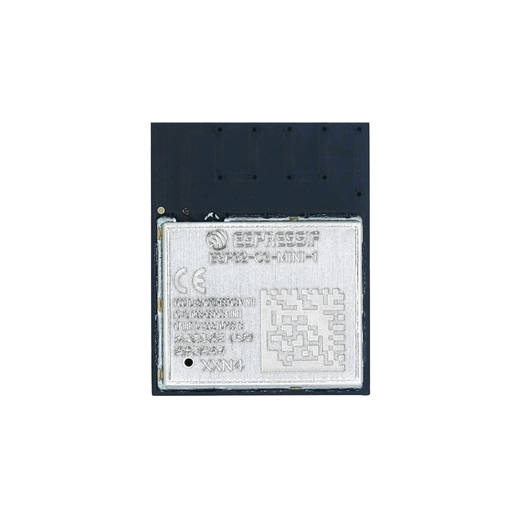
Module
The board uses the ESP32-C3-MINI-1 module, which integrates the ESP32-C3 chip, crystal, flash memory, and RF components in a small, shielded package. Ideal for compact wireless designs.
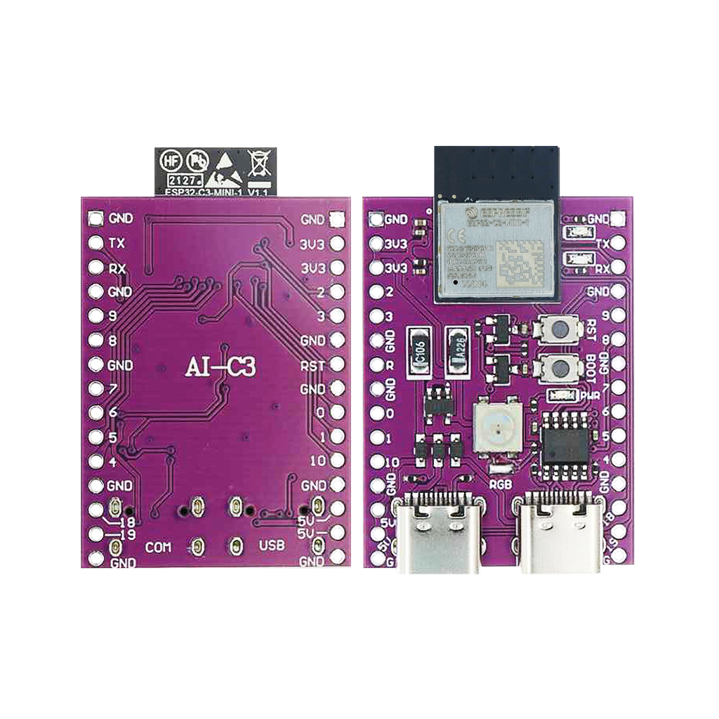
Development Board (DevKit)
The AI-C3 dev board breaks out all GPIO’s with labeled headers, includes an onboard USB-C port for power and programming, a WS2812 RGB LED, BOOT and RESET buttons, and a CH9102 USB-to-Serial chip. It’s designed for rapid prototyping, hobby projects, or advanced product development.
Designed for Connectivity and Control
The AI-C3 is packed with features for versatile development:
- Wi-Fi (802.11 b/g/n)
- Bluetooth 5.0 LE
- 22 usable GPIOs
- 12-bit ADC on 11 channels
- SPI, I2C, UART, PWM support
- Onboard WS2812 RGB LED
- USB-C programming + power
- Secure boot and flash encryption
Whether you’re creating smart devices, wireless sensors, or custom controllers — the AI-C3 has you covered.

** The AI-C3 pinout is available for download at the end of this post in high resolution – for free!
AI-C3 Pinout – GPIO Fundamentals
The AI-C3 exposes 22 GPIO’s, all fully configurable. But not all pins are created equal — some have special behavior or dedicated functions.
Input-Only Pins
None — all GPIO’s on the ESP32-C3 support both input and output.
Onboard RGB LED (WS2812)
The AI-C3 includes a built-in addressable RGB LED (NeoPixel) connected to GPIO8.
Applications: Use it for status indication, visual feedback, animations, or alerts. Control it with libraries like Adafruit_NeoPixel, FastLED, or custom drivers.
Advanced GPIO Features
Analog to Digital Converter (ADC)
The ESP32-C3 features a 12-bit ADC across 11 pins:
- ADC-capable GPIO’s: GPIO0 – GPIO10
- These can read analog voltages from sensors, potentiometers, and other input devices.
PWM (Pulse Width Modulation)
PWM is supported on all GPIO’s. Perfect for dimming LED’s, controlling servos, or generating tones.
I²C Communication
I²C is software-configurable on any GPIO. A common default setup on the AI-C3 is:
- SDA – GPIO8
- SCL – GPIO9
You can change these in code as needed.

SPI Communication
SPI is used for high-speed communication with displays, memory chips, and more. The AI-C3 default configuration is:
- MOSI – GPIO6
- MISO – GPIO7
- SCLK – GPIO4
- CS – GPIO3

UART Communication
UART0 is used for programming and serial output:
- TX – GPIO21
- RX – GPIO20
Additional UARTs can be mapped to other GPIO’s.
BOOT and RESET Buttons
- BOOT button: Connected to GPIO9. Hold low during power-up to enter firmware flashing mode.
- RESET button: Connected to the EN pin. Resets the chip when pressed.
AI-C3 GPIO Quick Reference Table
| GPIO | Special Function | ADC | PWM | RGB | Common Use |
|---|---|---|---|---|---|
| 0 | ADC1_CH0 | Yes | Yes | No | — |
| 1 | ADC1_CH1 | Yes | Yes | No | — |
| 2 | ADC1_CH2 | Yes | Yes | No | — |
| 3 | ADC1_CH3, SPI_CS | Yes | Yes | No | SPI CS |
| 4 | ADC1_CH4, SPI_CLK | Yes | Yes | No | SPI Clock |
| 5 | ADC1_CH5 | Yes | Yes | No | — |
| 6 | ADC1_CH6, SPI_MOSI | Yes | Yes | No | SPI MOSI |
| 7 | ADC1_CH7, SPI_MISO | Yes | Yes | No | SPI MISO |
| 8 | ADC1_CH8, I2C_SDA | Yes | Yes | Yes | RGB, I2C SDA |
| 9 | ADC1_CH9, I2C_SCL | Yes | Yes | No | BOOT, I2C SCL |
| 10 | ADC1_CH10 | Yes | Yes | No | — |
| 18 | USB_D- | No | Yes | No | Native USB |
| 19 | USB_D+ | No | Yes | No | Native USB |
| 20 | UART0_RX | No | Yes | No | Serial RX |
| 21 | UART0_TX | No | Yes | No | Serial TX |
Best Practices and Common Mistakes
- GPIO8 is used for the onboard RGB LED — avoid using it for other tasks unless you’re not using the LED.
- GPIO9 (BOOT) should be held low only when flashing new firmware.
- Use pull-up/down resistors as needed, especially for button inputs.
- Prefer ADC1 GPIO’s (0–10) for analog readings.
- Debounce mechanical button inputs in software.
- Avoid drawing more than ~12mA per GPIO.
How to Program the AI-C3
Development Environments
- ESP32-Homekit – My Own repository
- Arduino IDE – Easy to get started.
- PlatformIO – Modern, integrated workflow.
- ESP-IDF – Official SDK for low-level development.
Programming Pins
| Function | Pin | Description |
|---|---|---|
| TXD0 | GPIO21 | ESP to PC (Serial Out) |
| RXD0 | GPIO20 | PC to ESP (Serial In) |
| EN | EN pin | Reset ESP32-C3 |
| IO9 | GPIO9 | BOOT mode pin |
Steps to Flash Firmware
- Connect the board via USB-C.
- In Arduino IDE or PlatformIO, select “ESP32C3 Dev Module”.
- Click “Upload.”
- If flashing fails, hold BOOT (GPIO9) during upload.
Modern drivers on Windows, Linux, and macOS usually auto-detect the USB device and handle boot mode automatically.
Conclusion: Small Board, Big Power
The AI-C3 packs impressive wireless power and flexible GPIO’s into a small footprint. Whether you’re prototyping a smart home accessory, building a wearable, or experimenting with RGB visuals — mastering the AI-C3 pinout will help you build faster and smarter.
Download the AI-C3 pinout here in high resolution – for free*!
* Free to use under the MIT license — attribution is required.