
Electronics
0.91-inch OLED Display on an ATtiny85
The ATtiny85 is a compact and low-power microcontroller ideal for minimalist electronics.

The ATtiny85 is a compact and low-power microcontroller ideal for minimalist electronics. Whether you’re building a wearable, a sensor node, or a creative display, the ATtiny85 paired with a 0.91” OLED display delivers powerful functionality in an ultra-tiny footprint. In this guide, you’ll learn how to flash the ATtiny85, wire it up to an OLED display, and power it from a CR2032 battery.
What is the ATtiny85?
Minimalist MCU:
The ATtiny85 is an 8-bit microcontroller from Atmel (now Microchip) with 8KB flash, 512B SRAM, and 6 GPIO pins. It’s programmable via Arduino and ideal for low-power, space-constrained projects.
Features:
- 8-bit AVR RISC architecture
- Up to 20MHz clock speed (internal oscillator)
- 5 I/O pins (plus reset)
- I2C, SPI (via USI), ADC, PWM support
- Extremely low power consumption
- DIP-8 or SMD form factor
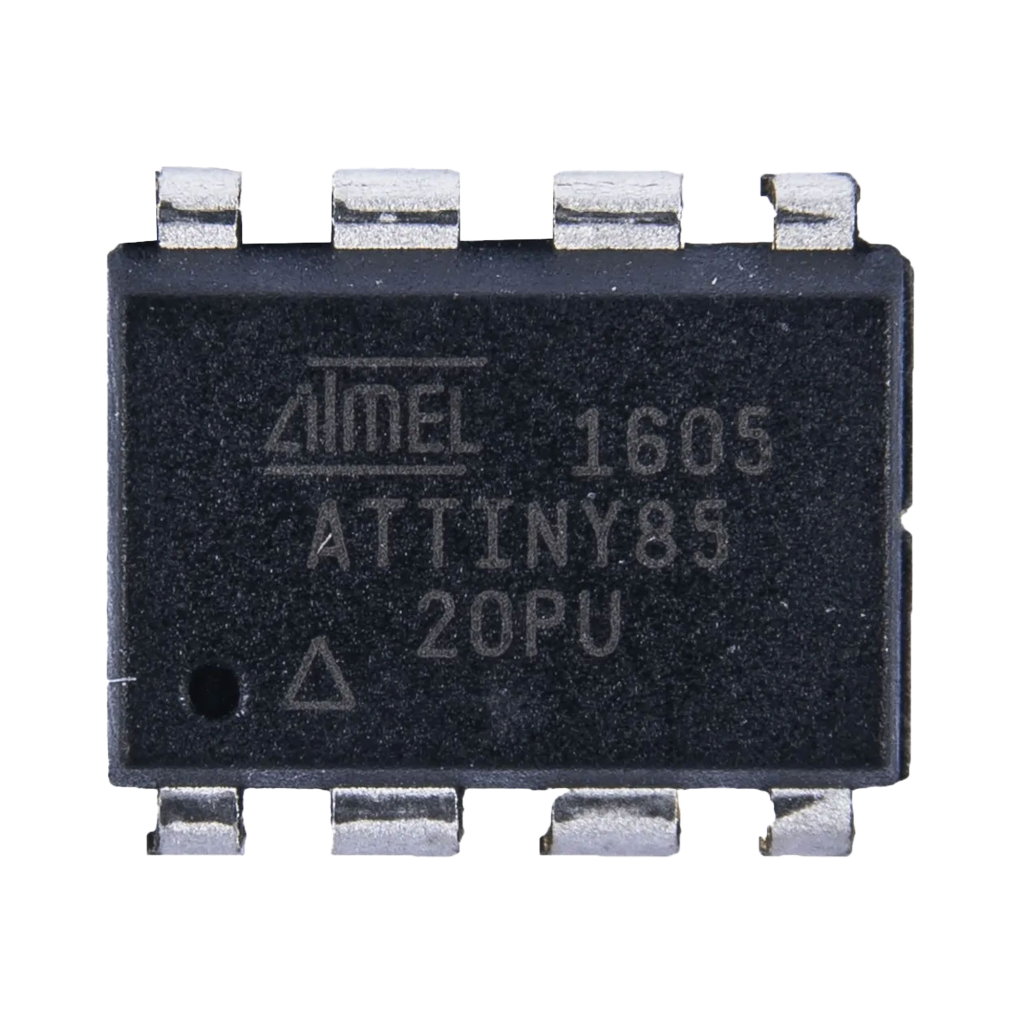
Flashing the ATTiny85 using an Arduino
Before connecting the OLED, the ATTiny85 must be programmed. You can do this using an Arduino Uno as an ISP (In-System Programmer).
Hardware Needed
- Arduino Uno
- ATtiny85 (DIP-8)
- Breadboard + jumper wires
- 10µF capacitor
- Arduino IDE installed
Steps
- Setup Arduino as ISP:
- Open the Arduino IDE.
- Load File > Examples > 11.ArduinoISP > ArduinoISP.
- Upload to your Arduino Uno.
- Connect the ATtiny85:
| Arduino Uno | ATtiny85 |
|---|---|
| Pin 10 | RESET |
| Pin 11 | MOSI (PB0) |
| Pin 12 | MISO (PB1) |
| Pin 13 | SCK (PB2) |
| 5V | VCC |
| GND | GND |

Note: Don’t forget to place a 10µF capacitor between RESET and GND on the Uno to disable auto-reset.
- Install ATtiny Board Support:
- Arduino IDE → Preferences → Additional Board URLs:
https://raw.githubusercontent.com/damellis/attiny/ide-1.6.x-boards-manager/package_damellis_attiny_index.json - Boards Manager → Install ATtiny by David A. Mellis.
- Arduino IDE → Preferences → Additional Board URLs:
- Board Settings:
- Tools → Board: “ATtiny25/45/85”
- Processor: “ATtiny85”
- Clock: “8 MHz (internal)”
- Programmer: “Arduino as ISP”
- Burn Bootloader:
Tools → Burn Bootloader - Upload Sketches:
Use Upload using Programmer (Shift + Upload icon)
Connecting the OLED Display (128x32, I2C)
This display uses the SSD1306 driver and communicates via I2C. It's a perfect fit for ATtiny85 thanks to its small size and low power usage.
Display Specs
- Resolution: 128x32 pixels
- Interface: I2C
- Operating voltage: 3.3V–5V
- Pins: VCC, GND, SCL, SDA
ATtiny85 Pinout
| Pin | Function |
|---|---|
| 1 (PB5) | Reset (or GPIO) |
| 2 (PB3) | GPIO3 / ADC3 |
| 3 (PB4) | GPIO4 / ADC2 / SCL |
| 4 | GND |
| 5 (PB0) | GPIO0 / MOSI / SDA |
| 6 (PB1) | GPIO1 / MISO |
| 7 (PB2) | GPIO2 / SCK |
| 8 | VCC |
I2C Connection
| OLED Display | ATtiny85 |
|---|---|
| VCC | VCC (Pin 8) |
| GND | GND (Pin 4) |
| SCL | PB2 (Pin 7) |
| SDA | PB0 (Pin 5) |

Note: I2C on ATtiny85 uses Software I2C (bit-banged). Libraries like TinyWireMAdafruit_SSD1306 + TinyWireM support this.
Powering with a CR2032 Battery
To make the project portable, we’ll power it using a 3V CR2032 coin cell.
Power Tips
- Connect CR2032 + to VCC, to GND
- Use a low-dropout voltage regulator if running peripherals at 3.3V with stable output
- Keep code optimized to minimize power draw
- Use
sleepmodes to extend battery life
Required Libraries (Arduino IDE)
#include <TinyWireM.h>#include <Tiny4kOLED.h>Install these via the Library Manager or GitHub.TinyWireMTiny4kOLED ondersteunt de SSD1306 128x32 displays.
Display Example: StudioPieters Project (Centered Text)
#include <TinyWireM.h>#include <Tiny4kOLED.h>void setup() { TinyWireM.begin(); // Initialize I2C oled.begin(); // Initialize OLED display oled.clear(); // Clear the screen oled.setFont(FONT8X16); // Use 8x16 font oled.on(); // Turn on the display // Line 1 (Y = 1) oled.setCursorCentered(1); oled.print(F("StudioPieters")); // Line 2 (Y = 2) oled.setCursorCentered(2); oled.print(F("ATTiny85 - OLED (I2C")); // Line 3 (Y = 3) oled.setCursorCentered(3); oled.print(F("Project"));}void loop() { // Static display, no refresh needed}ATtiny85 OLED Quick Reference
| Function | Pin | Notes |
|---|---|---|
| SDA | PB0 (5) | Use TinyWireM |
| SCL | PB2 (7) | Use TinyWireM |
| Power VCC | Pin 8 | 2.7V–5.5V (3V ideal) |
| Power GND | Pin 4 | Connect to ground |
| Display driver | SSD1306 | Compatible with Tiny4kOLED |
| I2C library | TinyWireM | Bit-banged implementation |
Best Practices and Common Mistakes
- Don’t use hardware
Wire.h, useTinyWireMfor I2C on ATtiny. - Keep OLED update rate low to conserve battery.
- Pull-up resistors on SDA/SCL are usually not needed (OLED module includes them).
- Don’t exceed CR2032 max current draw (~20mA continuous).
- Use
sleep_mode()inloop()to save power. - Mind ATtiny85 memory limitations (only 8KB flash).
Conclusion: Tiny MCU, Big Possibilities
The ATtiny85 + OLED combo is a powerful foundation for compact, battery-powered display projects. Whether you’re creating a branding badge, a sensor output monitor, or a creative wearable, this minimalist design packs a surprising punch.
Mastering the connection between the ATtiny85 and OLED unlocks a new tier of low-power, display-driven innovation, perfect for the maker who believes less is more.
Happy Building!