
Guide
ESP32-WROOM-32D Pinout
The complete pin reference for the ESP-WROOM-32D module: 34 programmable GPIOs, ADC/DAC, touch, RTC and the exact pins you can safely reuse.
- Dual-core Xtensa LX6
- Wi-Fi + Bluetooth
- 34 GPIOs
- 4–16 MB flash

Overview
This guide covers the ESP-WROOM-32D module itself: the shielded, castellated-pad component that integrates the ESP32 system-on-chip, a crystal oscillator and flash memory. It’s the module most ESP32 DevKitC-style development boards are built around, but the pin functions and dimensions below apply to the module, independent of any specific board.



No 802.15.4 radio on this chip, so Thread and Zigbee aren’t possible here: that needs an ESP32-C6 or H2 instead. (Only badges for protocols this exact chip actually supports are shown, no Wi-Fi 6/7 either: this is 802.11 b/g/n.)
Getting started
Most people using this module have it on a DevKitC-style development board, not the bare module by itself, and the three steps below assume that. If you’re wiring the bare module directly, see “Flashing pins” further down for how to connect a USB-to-serial adapter instead.
Hello World: blink an LED
The microcontroller equivalent of “Hello World”: GPIO2 toggles once a second, shown here in two different environments. Wire an LED (with a resistor) to GPIO2 if your board doesn’t already have one built in (most ESP32 DevKitC boards do).
#include "freertos/FreeRTOS.h"
#include "freertos/task.h"
#include "driver/gpio.h"

#define LED_PIN GPIO_NUM_2

void app_main(void)
{
    gpio_reset_pin(LED_PIN);
    gpio_set_direction(LED_PIN, GPIO_MODE_OUTPUT);

    while (1) {
        gpio_set_level(LED_PIN, 1);
        vTaskDelay(pdMS_TO_TICKS(1000));
        gpio_set_level(LED_PIN, 0);
        vTaskDelay(pdMS_TO_TICKS(1000));
    }
}
#define LED_PIN 2 // onboard LED on most DevKitC boards
void setup() {
pinMode(LED_PIN, OUTPUT);
}
void loop() {
digitalWrite(LED_PIN, HIGH);
delay(1000);
digitalWrite(LED_PIN, LOW);
delay(1000);
}ESP-IDF: build and flash with idf.py build flash monitor. Arduino IDE: install ESP32 board support first, see “Getting started” above.
Specifications
Official Espressif module specifications for ESP-WROOM-32D.
Compute
| Chip | ESP32-D0WD |
| CPU | Dual-core Xtensa LX6, up to 240 MHz |
| SRAM | 520 KB |
| Flash | 4, 8 or 16 MB (variant-dependent) |
Radio
| Wi-Fi | 802.11 b/g/n, 2.4 GHz |
| Bluetooth | v4.2 BR/EDR + BLE |
| Antenna | On-board PCB (IPEX variant available) |
Physical
| Operating voltage | 3.0V – 3.6V |
| Dimensions | 18 × 25.5 × 3.1 mm |
| Operating temperature | −40°C – +85°C |
| GPIOs | 34 programmable |

Pinout diagram
Every pin on the bare ESP-WROOM-32D module itself, not a specific development board. Boards built around this module (DevKitC and others) route these same pins to their own header labels, which may differ slightly from board to board.
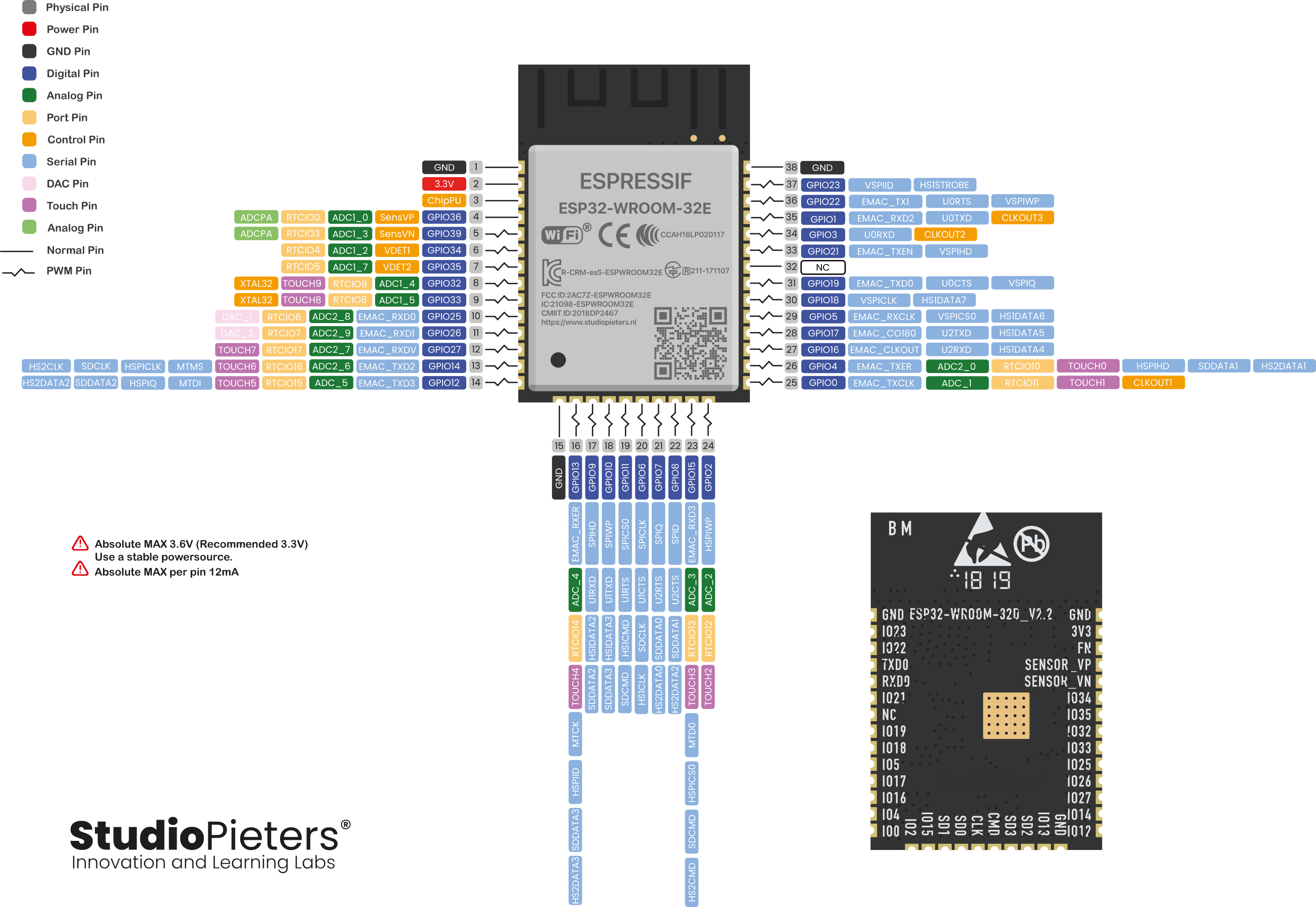
GPIO quick reference
ADC2 pins are unavailable while Wi-Fi is active, use an ADC1 pin (32–39) for analog reads alongside Wi-Fi instead.
| GPIO | Special function | ADC | DAC | Touch | RTC | Boot state |
|---|---|---|---|---|---|---|
| 0 | Strapping, Touch | ADC2 | No | Yes | Yes | Low/High |
| 1 | UART0 TX | — | No | No | No | High |
| 2 | Strapping, Touch, LED | ADC2 | No | Yes | Yes | High |
| 3 | UART0 RX | — | No | No | No | High |
| 4 | Touch, RTC | ADC2 | No | Yes | Yes | Free |
| 5 | Strapping, SPI CS | ADC2 | No | No | No | High |
| 12 | Strapping, Touch | ADC2 | No | Yes | Yes | Free |
| 13 | Touch | ADC2 | No | Yes | Yes | Free |
| 14 | Touch, SPI CLK | ADC2 | No | Yes | Yes | High |
| 15 | Strapping, Touch, SPI CS | ADC2 | No | Yes | Yes | High |
| 16 | UART2 RX | — | No | No | No | Free |
| 17 | UART2 TX | — | No | No | No | Free |
| 18 | SPI CLK | — | No | No | No | Free |
| 19 | SPI MISO | — | No | No | No | Free |
| 21 | I2C SDA | — | No | No | No | Free |
| 22 | I2C SCL | — | No | No | No | Free |
| 23 | SPI MOSI | — | No | No | No | Free |
| 25 | DAC1, RTC | ADC2 | Yes | No | Yes | Free |
| 26 | DAC2, RTC | ADC2 | Yes | No | Yes | Free |
| 27 | Touch, RTC | ADC2 | No | Yes | Yes | Free |
| 32 | Touch, RTC | ADC1 | No | Yes | Yes | Free |
| 33 | Touch, RTC | ADC1 | No | Yes | Yes | Free |
| 34 | Input only, RTC | ADC1 | No | No | Yes | Input only |
| 35 | Input only, RTC | ADC1 | No | No | Yes | Input only |
| 36 | Input only, RTC (VP) | ADC1 | No | No | Yes | Input only |
| 39 | Input only, RTC (VN) | ADC1 | No | No | Yes | Input only |
Flashing pins (UART0)
Used by a USB-to-serial adapter (or the onboard one) to upload firmware.
| Function | Pin | Description |
|---|---|---|
| TXD0 | GPIO1 | ESP32 → PC (output) |
| RXD0 | GPIO3 | PC → ESP32 (input) |
| EN | EN pin | Resets the ESP32 |
| IO0 | GPIO0 | Puts the ESP32 into flashing mode |
Safety notes
Before you wire anything up
- Never reassign the flash SPI pins (GPIO6–GPIO11), the module won’t boot.
- Don’t exceed 12mA current draw per GPIO.
- GPIO0, 2, 5, 12 and 15 are strapping pins, check their boot-time state before using them as outputs.
- GPIO34–39 are input-only, no internal pull-up/pull-down, add an external resistor if needed.
More guides
Keep building.
From ESP32 HomeKit accessories to Arduino and ATtiny reference guides, there’s more where this came from.
All guides