
3D printing
Building a 3D Printed Pit Droid, Part 5: The Neck, the Head and the Servo Test
Fitting the animatronic neck, testing all five servos on a servo tester, and working out what spring the head needs. A progress report with what I tested and what I did not.
- 3D printing
- Safety notes
- 9 min read
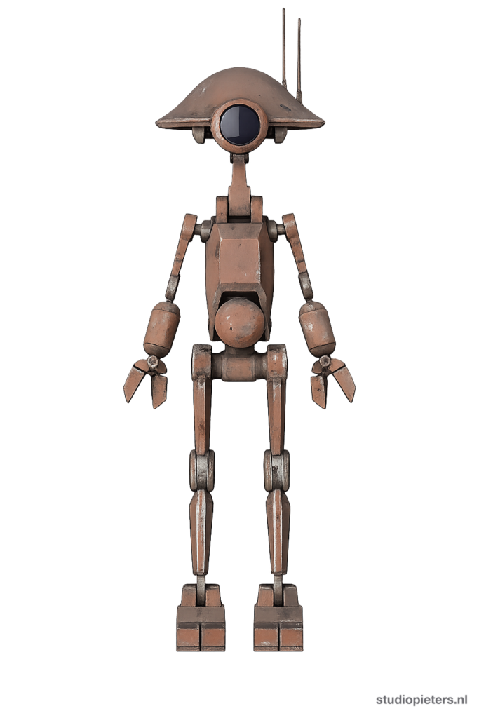
Hi, it’s Achim again. In Part 4 I filled, sanded and primed the head parts. In this part the head gets a neck, and I test the five servos that will move it. I also ran into the part that surprised me most: the spring.
This is a progress report, not a finished build. The neck fits together, the five servos work, and the spring is still open. I’ll tell you clearly what I tested and what I did not.
By the end you know what holds the neck together (no big bolts), how I tested the servos, and how I worked out what the head needs to stay up.
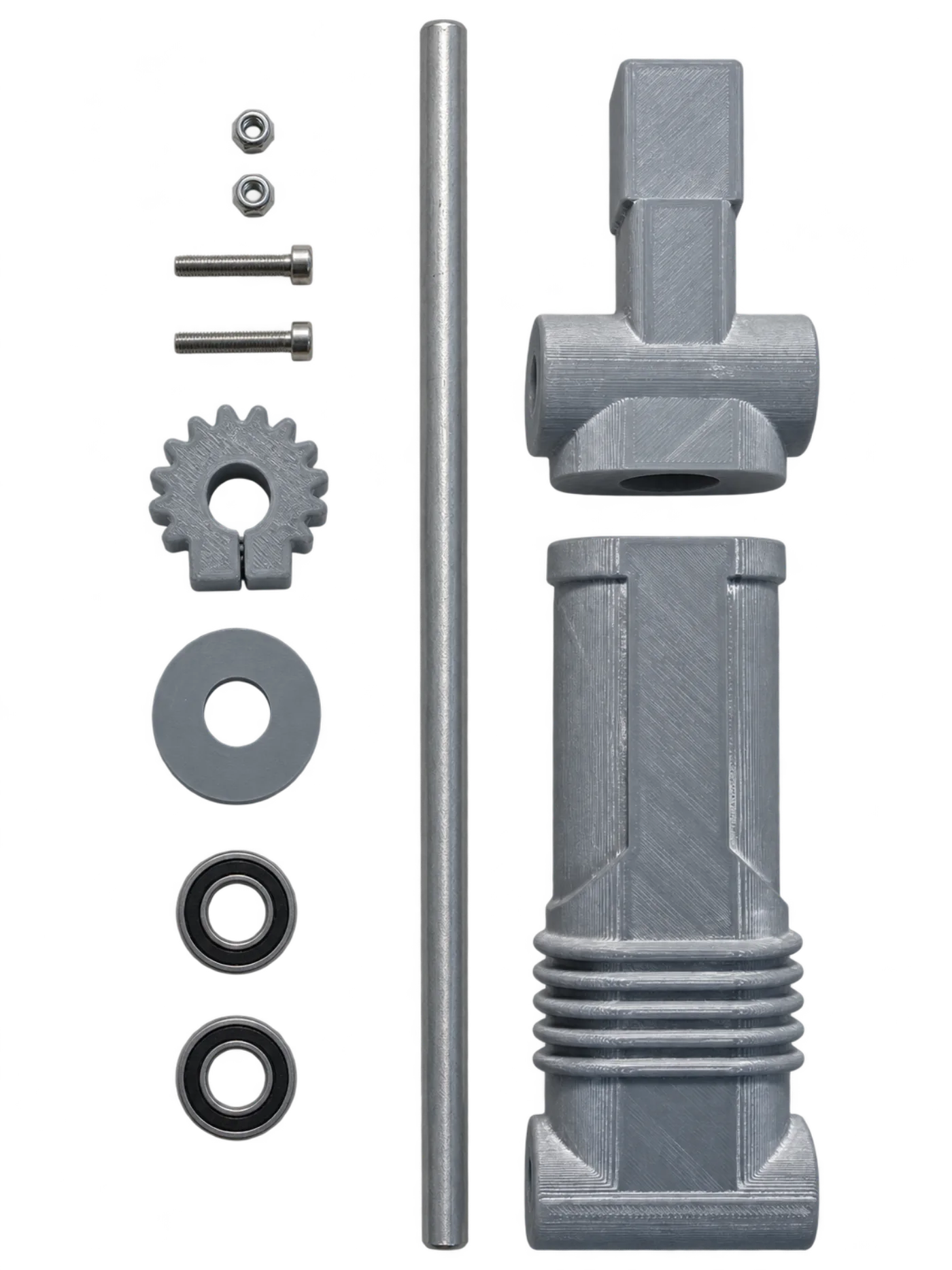
All the loose neck parts: tube, two bearings, clamp gear, disc, two bolts and nuts, and the neck pieces. The background is removed.
What Are We Doing?
| Goal | Fit the animatronic neck, test the five servos, find out what spring the head needs |
| Status | Neck parts test-fitted, servos tested on a tester, spring not chosen |
| Difficulty | Intermediate: small parts and a bit of maths |
| Parts | 1 aluminium tube, 2 bearings, 2 pins, 2 bolts with nuts, 5 servos |
How the Neck Works: No Big Bolt
I expected a big bolt under the head. There isn’t one. The animatronic info sheet from Droid Division shows two movements, and each one works differently:
- Tilting (nodding): the upper neck tilts on two steel pins of 6 x 25 mm. They go through the cross tube of the upper neck. The pins can be steel, aluminium or brass. The normal “Upper Neck Joint” (a 75 mm M6 bolt) is not needed with the animatronic head. Don’t print and fit both.
- Turning (shaking the head): the head turns on two 6800-2RS bearings (10 x 19 x 5 mm) and a tube of 10 mm as the axle. A servo turns it, either through a servo arm or through gears.
- Neck to torso: only here do you need real bolts: two M6 bolts with square M6 nuts. The sheet does not give a length. Check it dry before you glue anything.
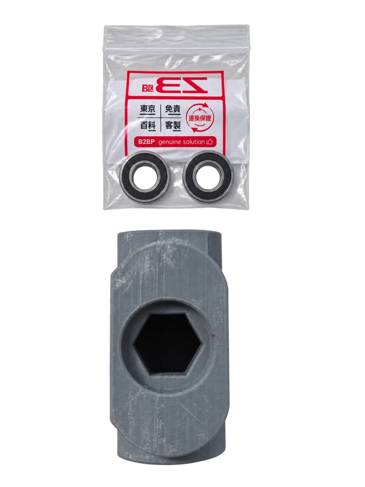
The two 6800-2RS bearings next to the upper neck.
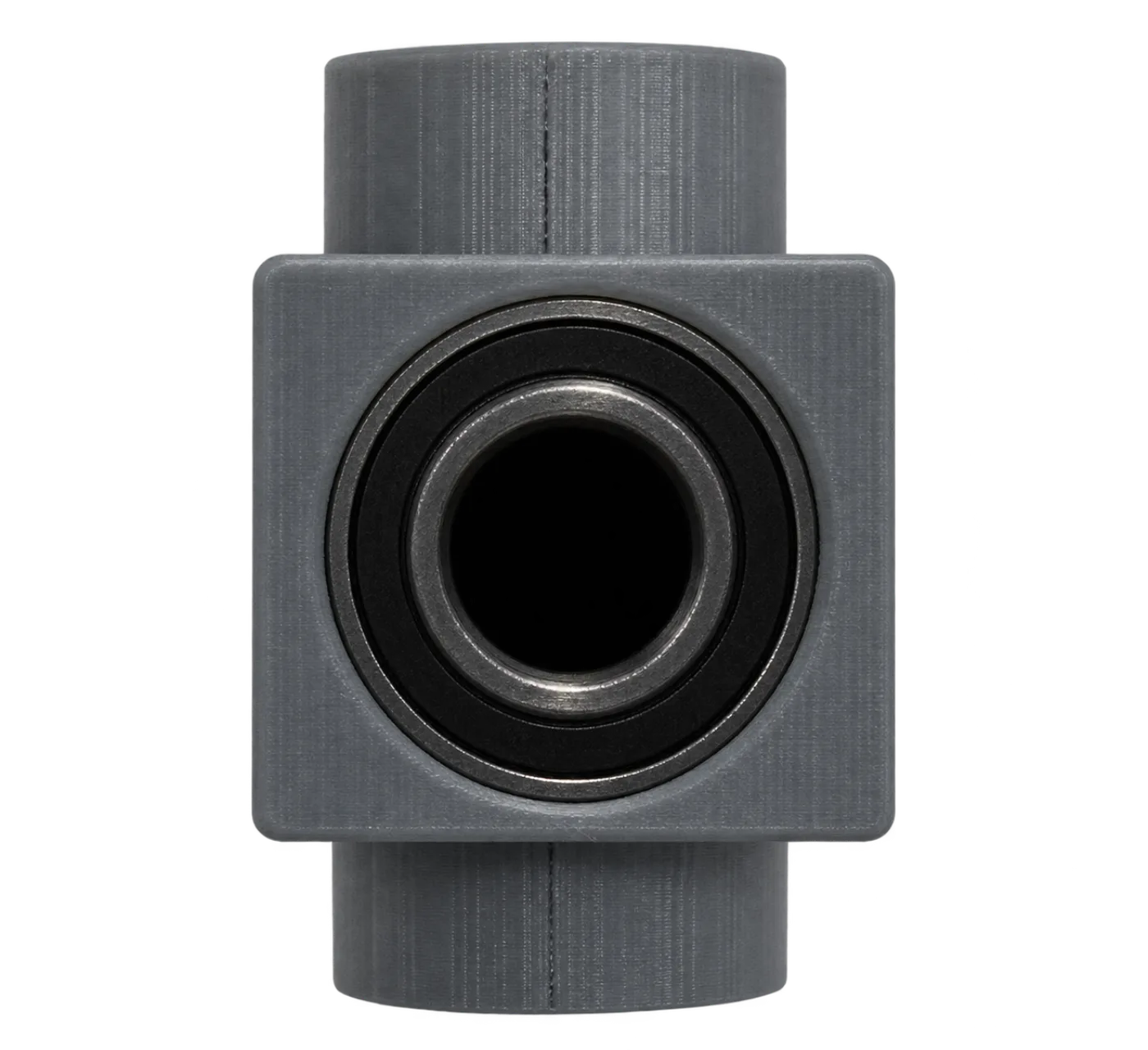
One bearing pressed into its recess.
I measured the upper neck in the model: it has two round recesses of 19.0 mm across and 5.0 mm deep, one on each side of a hexagonal passage. That is exactly a 6800-2RS. I did not press the second bearing in yet, so I can’t tell you if a bearing goes in without sanding. Printed parts differ 0.1 to 0.3 mm from the model.
The Tube
The sheet asks for a tube of 10 mm outside diameter, 150 to 280 mm long. You glue it into the lower neck and let it stick out 20 to 22 mm above the upper neck. It has to go at least halfway down the lower neck. Bevel the ends so they don’t cut the wires.
I use aluminium, 10 x 1 mm, 240 mm long. The 1 mm wall leaves 8 mm inside, enough room for the wires from head to body. I haven’t glued it. Do a dry fit first.
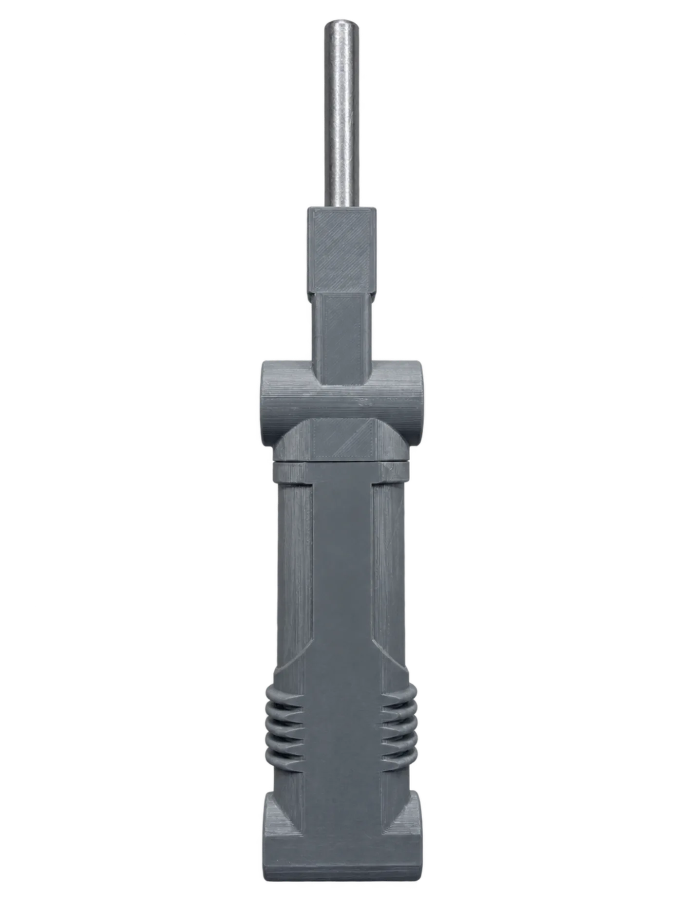
The tube in the neck, dry fit, no glue.
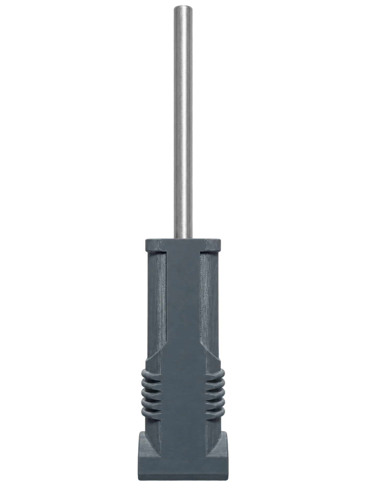
The lower neck with the tube.
The Turning Mechanism: Gears and Two Small Bolts
The sheet gives two ways to turn the head. I chose the gear version. A clamp gear with a slit sits on the tube. You squeeze it with two small bolts, which is called a pinch bolt.
The sheet doesn’t give the bolt size. So I measured the model first. The gear’s holes are 3.0 mm, 7.5 mm apart, and I measured a hole length of 12.7 mm. That told me M3 and about 12 mm. In real life M3 x 22 mm with a hex nut fits the printed gear. So the length I measured was not the whole bolt, probably because of a nut recess I did not find in the model. The lesson: the model gives a start, the print gives the answer.
For the arm version of the same part (DDPD23COServoArm) I measured a 10.06 mm hole, a 1 mm slit and 3.0 mm holes, and guessed M3 x 16. I did not use that version, so that guess is untested.
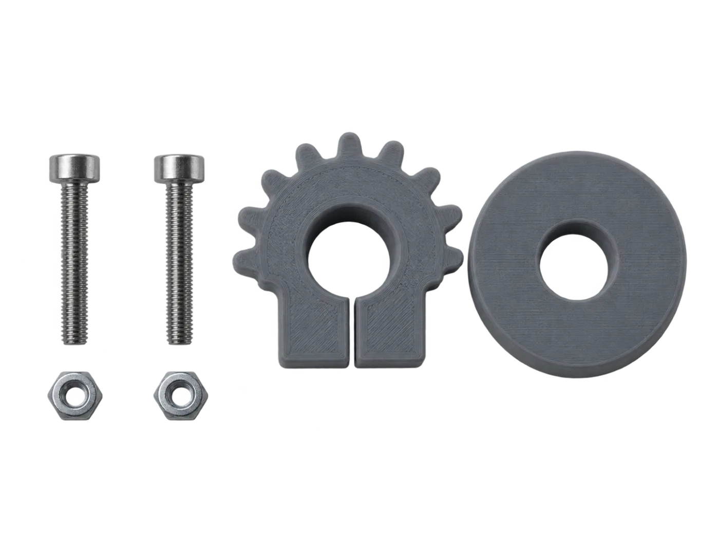
Clamp gear, disc, two M3 x 22 bolts and two hex nuts.
The Servo Test
Before any servo goes into the head, I test it on its own. I used a cheap servo tester with a power supply of 5 V. This is what I did with each of the five MG996R servos:
- Measure the supply voltage first. Mine is a 5 V 10 A supply (type S-50-5).
- Plug the servo into one of the output columns (1 to 7). In every column the top pin is the signal (S), the middle pin is plus and the bottom pin is minus. Orange or yellow goes on S, red in the middle, brown or black at the bottom.
- Power goes in the separate power column at the end of the header (4.8 to 6 V), not in an output column. This is easy to mix up.
- Turn the knob by hand and watch if the servo moves smoothly.
- Then run the sweep for a minute or two.
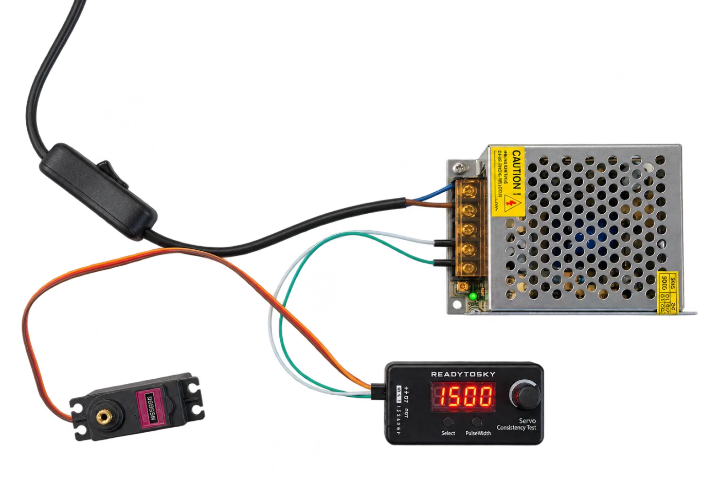
The test setup: the supply, the servo tester and one MG996R, display on 1500.
The result, from my own notes:
- All five servos are fine. They move smoothly, with no jumps.
- The range is about 120 degrees (my estimate, I did not use a protractor).
- The first servo was not warm after the sweep. I did not write down the temperature of the others.
- The voltage stayed at 5.04 V while the servos moved. This is without load: no arm and no horn on the servo. I did not measure under load.
What I did not note: which servo has which label, the noise, and the sweep time. I’ll label them before I mount them.
Careful with the supply
The S-50-5 has mains voltage on its input. Don’t touch it while it’s plugged in, and don’t open it. I use a switch on the mains cord so I can turn it off.
The Spring
The animatronic info sheet says only that “a light tension spring is useful to balance some of the head weight, also helps stop the head tilting forward when the power is turned off”. It doesn’t say which spring. So I measured my own head.
Here is where I made the mistake of the week. I mixed up weight and force.
- The head alone weighs 800 g on a scale, without paint.
- My first measurement with a luggage scale gave 30 g, much lower than I expected. A calculation from the weight and the lever gave several newtons. The two did not match, and I did not trust either.
- Then I measured again, and wrote 175 g. That is not the weight of the head. It is the force at the eye that holds the head upright, with the lens, the controller board and the wires already in. It is a force, not a weight, and I only worked that out afterwards.
The numbers I measured:
| What | Value |
|---|---|
| Head weight | 800 g (scales) |
| Pull at the eye to keep the head upright | 0.175 kg, about 1.7 N |
| Distance eye to tilt axis | 19.5 cm |
| Distance spring hole to tilt axis | 12 cm |
| Tilt range | about 30 degrees forward and backward |
| Spring length in the upright position | 70 mm, at right angles to the arm |
The maths, step by step:
- Torque of the head: 1.717 N x 0.195 m = about 0.335 Nm.
- To balance it completely at a lever of 0.12 m, the spring needs 0.335 / 0.12 = about 2.8 N.
- I don’t want it to balance everything, the servo should do the work. I aim for 60 to 70%, so about 1.7 to 2 N (170 to 200 g) at 70 mm.
These are estimates. I did not test a spring and I did not measure at 30 degrees in detail (my luggage scale gave the same reading as upright, but it may be too coarse for that).
On the sheet the spring runs from a post on the head base to the servo horn on the upper neck. The end at the horn moves with the servo. So the spring length changes with the tilt angle and the horn length. I haven’t measured the horn length yet.
What I’ll buy: the sheet doesn’t give a spring, so I don’t want to buy one at random. I found a Hornbach box with a 200-piece assortment of tension and compression springs for EUR 12.95. The page gives no wire thickness or length, so it is a gamble until I measure what is inside. I’ll sort the springs, measure the length, the outer diameter and the wire thickness, and test the force at 70 mm and at the ends of the range on the luggage scale. Plan B is a pack of six small stainless steel springs (0.6 mm wire, 6 mm outer diameter) from AliExpress, but that takes 22 to 29 November to arrive.
The lesson: measure on the real model, at the spot where the spring will sit, and measure only when the lens, the controller and the cables are in. They shift the centre of gravity.
Not Tested Yet
I want to be clear about this:
- The spring: not chosen, not bought, not tested.
- The servos in the neck: tested alone on a tester, not on the PCA9685 and not in the model.
- The bearings pressed into the upper neck, and the tube glued into the lower neck.
- The Waveshare board: not here yet, so no camera, no microphone and no speaker test.
- The servos under load, with an arm or the head on them.
- The M6 bolt length from the neck to the torso.
Mistakes I Want You to Avoid
- Mixing up weight and force. A scale gives grams, the spring needs newtons at a distance. Write down what you hang on the scale and where.
- Trusting the first number. I had 30 g, 800 g and 175 g, and each was a different thing.
- Plugging a servo into the power column of a servo tester instead of an output column.
- Buying a spring before measuring. A spring that is too stiff can break your servo gears or stop the head from moving.
- Gluing the tube before the dry fit.
Words Explained
- Pinch bolt: a bolt that squeezes a slit clamp around a tube so it doesn’t slip.
- Tension spring: a spring that pulls when you stretch it.
- Torque: a turning force. Force times the distance to the axis.
- Newton (N): a unit of force. 1 N is about 100 g of pull.
- Servo tester: a small board with a knob that sends a servo signal, to test a servo without a microcontroller.
- Sweep: the servo moves back and forth by itself between two end positions.
Conclusion: The Head Has a Neck, Not Yet a Spring
The neck parts fit together, and all five servos are healthy. The spring is the open question, and I’ll only choose it after I measure what is in that assortment. If the Waveshare board has arrived by then, the next part also covers the first test with it.
Next up: the spring test and the first servo on the PCA9685.
Previous: Part 4: Sanding and Preparing
Unofficial fan project
Pit Droid and Star Wars are trademarks of Disney/Lucasfilm. This site is not affiliated with, endorsed by or sponsored by Disney. The droid in this series is based on the PD-23 files by DroidDivision (Dave Moog), which are used under a single-person licence.
Related
 Electronics
Halloween Jack O’ Lantern
* This project is featured on Instructables
Read more
 Electronics
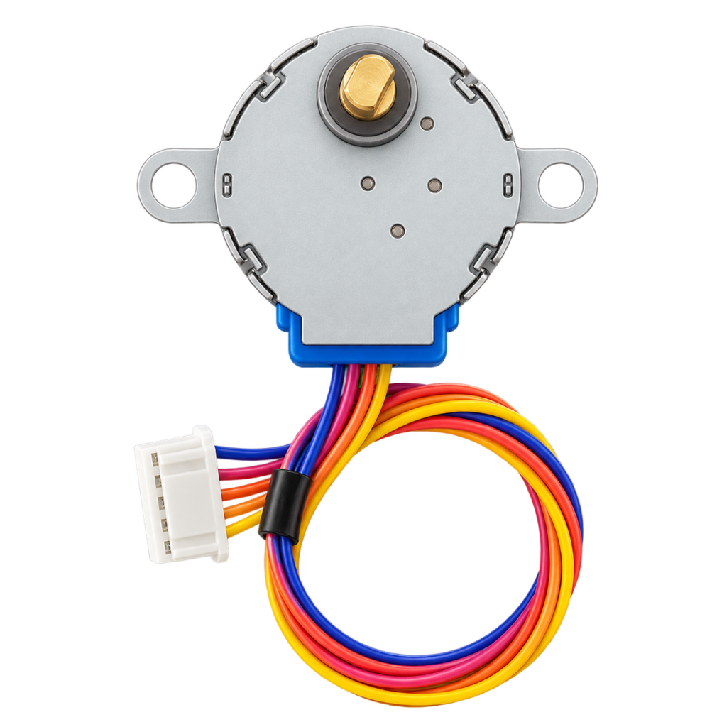
Blinds over MQTT with a NodeMCU and a Stepper Motor
A NodeMCU that moves blinds with a 28BYJ-48 stepper motor, set as a percentage over MQTT and used from Homebridge.
Read more
 Electronics
Halloween Jack O’ Lantern V2
After the success of my previous project, the Halloween, Jack O’ Lantern – many of you asked for something even more dynamic, with smoother flame transitions and more LED action.
Read more
More projects
Keep building.
Electronics, 3D printing and CNC builds, documented from the first idea to the last screw.
All projects